What's new

Model 2 to JAMMA harness

Bumping this thread because I have a few questions:

I own two Model2 to JAMMA cable interfaces and neither of them seem like they will play well with my Supergun.

Both of the harnesses seem to have setups to use external audio, and not the audio through a typical JAMMA connector, so I won't get any sound.

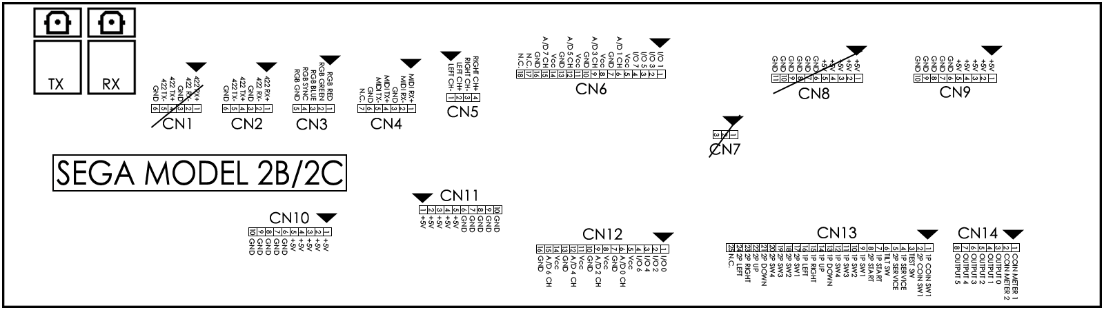
My grave concern is regarding the controls. For Fighting Vipers and Sonic the Fighters, there are only 3 button inputs I need to worry about, not counting coin/service/start buttons.

However, for other Model2 games, there can be up to 8 buttons. How would this be supported on a Supergun?

Also, Would it be possible to create a PCB board with headers that would mount onto the filter board with a JAMMA extrusion so an extension cable could be used to plug into the Supergun? I'd very much like to design and produce boards like that if it would simply done in an EAGLE CAD program. I don't see why it wouldn't be possible. An extension cord would obviously have to be used though to connect to the JAMMA cabinet/supergun.
 
I was able to successfully wire this up (and I did eventually figure out how to order from JST)
I also did my own harness for connecting my VF2 to jamma, however I get the not enough power error on screen.
Can you please give me more details on how you wired the ATX power supply to your system? Thats the only thing im missing.

Thanks
 
for other Model2 games, there can be up to 8 buttons
which games use more than 3 buttons per player?

more details on how you wired the ATX power supply to your system
you take the ATX connector pinout:
atx-pinout.png

To force the ATX PSU on you need to hook "PS_ON#" to any of the "COM" (AKA Ground) pins.

then you run the rest of the wires to the correct pins on the model 2 board power connectors:

the hard part is the fact that there are only 5 +5V pins on the ATX connector and there are 15 +5V input pins on the Model 2 filter board. The filter board uses JST NH connectors which only support up to 22awg wire I believe. so what you'll want to do is crimp 2 22awg wires together on each 5V pin of the atx connector so that you have enough to fully populate the model 2 connectors. and then start tapping +5V pins on other connectors on the power supply, if there are CPU and GPU power connectors use those and failing that you can start using the 4-pin "molex" connectors.
sega_model2_b_c_pcb_arcade_filter_board_pinout.gif
 
Last edited:
thank you! just to make sure I get this right.

So I populate all the +5V and GND only right?

20 x GND
20 x +5V

I do not need to connect anything else from the ATX to model 2?
the rest goes to my jamma converter
 

Attachments

  • sega_model2_b_c_pcb_arcade_filter_board_pinout2.jpg
    sega_model2_b_c_pcb_arcade_filter_board_pinout2.jpg
    149 KB · Views: 306
you do not populate CN8, that's an output connector for additional hardware (hence why it has the line through it).

you will also need +12V but it just 1 wire that goes directly to the cooling fan on the outside of the case.
 
ok perfect, so just C9-10-11 and 1 x 12v to the fan. Easy enough! I will try to get that done, been on my list for a while. thanks again
 
Hello there.

I recently bought a Sega Model 2 B CRX board.

I want to plug it to my New Net City, since it has that glorious tri synch monitor with stereo sound, and I made a Jamma harness for it.

Controls will go through my Jamma harness, audio through the RCA plugs, and Video through the VGA cable. That's the easy part.

I am more worried about the power supply, since the standard NNC PSU gives 5V 10A, when a NVS-4000, for instance, gives 5V 12A.

Will the standard NNC PSU be enough, or should I get an external PSU?
 
I don't think anyone has measured the power draw of a Model 2 stack.

I would try to run it with your current PSU.

Alternatively, try to find a SUN PSU with a 15A +5V rail. Easy drop-in solution.

https://www.arcade-projects.com/threads/sun-psu-capacitor-maps.5425/
Yeah I found a 15A PSU for 50€, so I did not hesitate. Moar power. And painted it Black because it was getting rusty.

IMG_20241201_145236.jpg


I have the Model 2, The PSU, I've made the audio and video harness. Still have to make the control harness and most importantly the PSU harness.

By the way, I've seen multiple harnesses for sale, and some of them only have 2 connectors for PSU, some have 3; some have all the GND and +5V wires connected on the JST 10 pins connectors, some only have like 2 or 4 wires.

I can't seem to figure out what is mandatory to make it work and what's not. I've tested the filter board and all the +5V pins on each individual connector are connected together, but each connector works individually.
 
I would check original schematics and copy the wiring from them.
 
Back
Top