jgarrettcorbin
Beginner
Hey everyone! I'm excited to join this community. I recently found a Sega Aero City cabinet on the side of the street in my neighborhood. I've been wanting an arcade machine with a CRT for a while now, so I took it home.
I rigged up a Raspberry PI to output 15khz RGB and with some tweaking I got the monitor to look amazing. The only issues were that I lost the blues every once in a while. I light tap on the neck board with a drum stick made them come back, so I figure it was a cracked solder joint, or a tube socket issue, so no big deal there. There was also some minor blooming. I thought I'd do a cap replacement to hopefully improve this.
So I did a cap kit. I want to preface this by mentioning that I've been soldering for the better part of 20 years now. I used to work on a lot of tube amplifiers, but now most of what I solder is under a microscope. This isn't to say that I didn't make a mistake here, because thats entirely possible, but I didn't do this with a $10 radio shack soldering iron.
After installing everything back into the chassis, I fired it up and the picture was way too small and kind of dim. Adjustments didn't help. Something was wrong. If I leave it on, eventually the picture would stretch out horizontally, and it made the worst squeal i've ever heard in my life. This seems temperature related because it usually takes 10 minutes or so for it to happen. If I unplug for a few seconds, it'll be fine for a few seconds and then happen again. If I wait until it cools down, it takes 10 minutes to happen.
I stuck an oscilloscope on the collector of HOT and it was running at 24.3Khz? To my limited knowledge, this should be around 15khz. Just as a test, I moved the tap to the 24khz plug on the board just to see what happens. I get the same frequency, although the waves look a little different, and vertical collapse on the screen.
With a 15khz signal input, I just get vertical collapse, with the horizontal line still not being full width.
I have since checked over my work multiple times. I verified the new caps against their original value. I verified the polarity is correct, I checked all of my joints and places I reworked to make sure there were no dry joints or bridges. Everything seems good. I was hoping someone could point me in the right direction as to what could have happened, or at least what part of the circuit I should be looking at. I know a decent amount about vacuum tubes, but everything I know about CRTs I've learned in the last 2 weeks.
Thanks everyone, and I'm excited to be a part of the community.
attached from left to right:
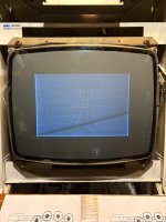
raster on cold start, picture too small.
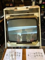
if left on for 10+ minutes, accompanied by awful high pitched sound.
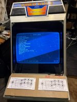
Picture before I did the recap.
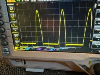
Oscilloscope probing the HOT. 24.3khz.
I rigged up a Raspberry PI to output 15khz RGB and with some tweaking I got the monitor to look amazing. The only issues were that I lost the blues every once in a while. I light tap on the neck board with a drum stick made them come back, so I figure it was a cracked solder joint, or a tube socket issue, so no big deal there. There was also some minor blooming. I thought I'd do a cap replacement to hopefully improve this.
So I did a cap kit. I want to preface this by mentioning that I've been soldering for the better part of 20 years now. I used to work on a lot of tube amplifiers, but now most of what I solder is under a microscope. This isn't to say that I didn't make a mistake here, because thats entirely possible, but I didn't do this with a $10 radio shack soldering iron.
After installing everything back into the chassis, I fired it up and the picture was way too small and kind of dim. Adjustments didn't help. Something was wrong. If I leave it on, eventually the picture would stretch out horizontally, and it made the worst squeal i've ever heard in my life. This seems temperature related because it usually takes 10 minutes or so for it to happen. If I unplug for a few seconds, it'll be fine for a few seconds and then happen again. If I wait until it cools down, it takes 10 minutes to happen.
I stuck an oscilloscope on the collector of HOT and it was running at 24.3Khz? To my limited knowledge, this should be around 15khz. Just as a test, I moved the tap to the 24khz plug on the board just to see what happens. I get the same frequency, although the waves look a little different, and vertical collapse on the screen.
With a 15khz signal input, I just get vertical collapse, with the horizontal line still not being full width.
I have since checked over my work multiple times. I verified the new caps against their original value. I verified the polarity is correct, I checked all of my joints and places I reworked to make sure there were no dry joints or bridges. Everything seems good. I was hoping someone could point me in the right direction as to what could have happened, or at least what part of the circuit I should be looking at. I know a decent amount about vacuum tubes, but everything I know about CRTs I've learned in the last 2 weeks.
Thanks everyone, and I'm excited to be a part of the community.
attached from left to right:
raster on cold start, picture too small.
if left on for 10+ minutes, accompanied by awful high pitched sound.
Picture before I did the recap.
Oscilloscope probing the HOT. 24.3khz.