MV1FT Battery Corrosion

alexqts

Beginner
Joined
Mar 18, 2026
Messages
21
Reaction score
7
Location
London
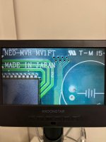
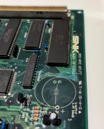
Just got an MV1FT that has some battery corrosion. I have removed the battery and cleaned the board. I am sure it will need repairs...

What is the best way to go about removing the corrosion from the board in the least invasive way? I heard diluted vinegar could be an option.

Many thanks
 

Attachments

  • 1.jpg
    1.jpg
    157.8 KB · Views: 45
A fine fiber pen, alcol, check disconnected track and solder a bridge wire from a chip to another.
This is what i doing with my pcb.
 
It's a corrosive oily substance. You need to use a good degreaser and a toothbrush to get it all off. Once clean you'll need to spend time checking trace continuity and patching.
 
Thanks,

Has cleaned up better than it looked it would.

Tried a boot and it just has garbled squares and clicking sound. Replaced with Diag BIOS and clicking stopped, but still garbled screen. Also screen seems to respond to moving the cart around.

Guess it is time to get the multimixer out!

Looking at the chips near the battery, most seem audio related - would broken traces to the YM610 / Z80 / Z80 RAM etc cause a garbled screen? I would assume it must be the video chips that are bad?
 

Attachments

  • 1.jpg
    1.jpg
    150 KB · Views: 26
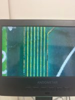
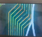
OK so going in for a much closer look and about 8 of the traces are bad.

They are traces running between NEO-C1 to NEO-D0 via BR6116-100 marked on the board as VG2450THD, a resistor array?

Assuming this must be the issue? If anyone has any tips for repairing this - I am guessing 30awg and go point to point, rather than trying to repair the traces themselves.
 

Attachments

  • 1a.jpg
    1a.jpg
    137.1 KB · Views: 20
  • 2a.jpg
    2a.jpg
    292 KB · Views: 21
They are traces running between NEO-C1 to NEO-D0 via BR6116-100 marked on the board as VG2450THD, a resistor array?
VG2450THD is/was the (now removed) battery. BR6116-100 is an SRAM chip, (it's marked 6116 on board). You might want to see if there's any nastiness underneath that chip.
 
OK so going in for a much closer look and about 8 of the traces are bad.

They are traces running between NEO-C1 to NEO-D0 via BR6116-100 marked on the board as VG2450THD, a resistor array?

Assuming this must be the issue? If anyone has any tips for repairing this - I am guessing 30awg and go point to point, rather than trying to repair the traces themselves.
Yes point to point with AWG 30 I have done the same. I try also to repair the trace but the trace are really thin.
 
OK so going in for a much closer look and about 8 of the traces are bad.

They are traces running between NEO-C1 to NEO-D0 via BR6116-100 marked on the board as VG2450THD, a resistor array?

Assuming this must be the issue? If anyone has any tips for repairing this - I am guessing 30awg and go point to point, rather than trying to repair the traces themselves.
Yeah. Just get some wire and patch them.
 
Check the traces to the Backup RAM as well... If you have problems with the R/W, /OE, or /CE lines the CPU will not start up and you'll be left with the 'click of death'
 
Thanks, will try. Currently waiting for some soldering supplies to show up.

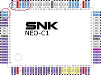
Problem appears to be the traces from NEO-C1 to the SD pins on the 6116 SRAM chip circled below. From reading the 6116 looks to be sound related.

Can anyone confirm if this would cause the garbled screen, or am I looking for something in addition to this? The rest of the board looks good so far. I get no clicking with Diag bios, just bad screen.
 

Attachments

  • NEO-C1_pinout.png
    NEO-C1_pinout.png
    144.1 KB · Views: 23
Last edited:
I managed to get the board booting after replacing a ton of broken traces.

Unfortunately it has a Z80 error, but more importantly the Start / select buttons seem to be permanently on. I have checked traces and they are all fine.

Sadly I cannot access the test screen to see exactly what buttons are being pressed, but when loading a game on Unibios 4.0 the cheat menu instantly appears.

I have 5v showing to all of the controller input pins on C1 & jamma edge, and they pull down to 0 when testing buttons. I can only conclude that the c1 is failed internally and showing a permanent low signal to the bus for some / all inputs?

Anyone have any ideas? It was great to revive the board but starting to think it was shelved due to the bad C1 :unsure:
 
Back
Top