mv1fz video ram error

marcao_cfh

Student
Joined
Oct 15, 2025
Messages
43
Reaction score
9
Location
Brazil
Hello everybody. How's going?

I have a MV1FZ here with the video ram error. When I use the stock bios, I get
Video RAM Error
Address 00008000
Write 5555
Read 8955

Diagnostics bios gives me
VRAM Data (0000)
Address: 008000
Actual: 8900
Expected: 0000

There's no sign of corrosion or broken traces on the board. Also, Unibios gives me the crosshatch screen, but I didn't tried it with a game to check how it goes.

Any clues on what to check?
 
Thanks! I'll try to replace it tonight, and hope there's no other issues with this board.
 
The address in the errors is 008000, which would actually put it in the 2K VRAM chip range. So the issue is with 2K VRAM Upper chip instead.
Ah crap, I was happy the issue could be a 32K VRAM and not a 2K VRAM. They are a pita to remove and I don't think I have any spares here, need to check tomorrow.

Ok, so I removed the 2K Upper chip and tested it, it's indeed bad. I'll be back with more news tomorrow.

Thanks so far!
 
Ok, a update, and not a good one...

I got a 2K VRAM chip from a donor board, tested it on my T48 programmer and it's good. Then I installed a socket on the MVS, inserted the chip, and got a glitched screen with something unreadable. It seems to act exactly the same with or without the chip inserted. I can't be so sure because the screen is really unreadable.

Since this chip is a pita to remove, I may have damaged the board while removing it, or may have created some cold solder joint (I used a solder sucker for almost all the solder and a heat gun for the solder I couldn't remove). Need to inspect the board when I have more free time. But I'll post a photo of the screen later.
 
If you damaged the board removing it, you might be in over your head. I've been down this road. For beginners it's never as simple as, "Oh, let me just replace this ram."

The board may have been the problem to begin with. This is a kind of progress, because now you know you need to get the multimeter out and inspect all the connections to that ram.
 
I have a good amount of experience on soldering single layer pth and smd, but I rarely do double layer pth and some pins are not so easy to desolder due to solder on both layers. Add a gnd plane to the equation, and removing solder from a double layer pth can be hard.

I removed as much as solder I could by applying new solder and then using a solder sucker, but some pins just got stuck, so I used a heat gun to melt the leftover solder and remove the ram using a tweezer. I'd bet I damaged one (or more) traces while removing the ram.

Maybe there were other issues within the board, but the ram was indeed bad. I tested it on my T48, but now things are worse. Before removing the ram, at least I could read the error, now every text is glitched. So I started with a issue and created a different one while trying to fix the initial issue lol. Luckily I know somebody who can fix the board in case I can't, but I won't give up.

I'll start by removing the socket and checking for scratched traces (I know I should have done this before soldering the socket, but it was late night when I was trying to fix it), then checking connections with the multimeter. And it's probably worth a reflow on the NEO-B1 and LSPC2-A2 chips since they're related to the graphics.

Hope I can bring some good news on this board soon. Meanwhile, I have another board with a palette ram error I hope sould be easier to fix, so I'll post more info on it later and will troubleshoot this board when I have more free time.
 
I never tried Chip Quik. It doesn't seems to exist in my country, and buying overseas now is not a easy task due to high taxes/fees and our customs refusing lots of packages based on what's inside the package or even what's written in the invoice.
 
I'll start by removing the socket and checking for scratched traces (I know I should have done this before soldering the socket, but it was late night when I was trying to fix it), then checking connections with the multimeter.

Hmm ... May I suggest you test the connections with a dmm first? Then you might not have to remove the socket.

Let me know and I'll take some photos on a mv1fz with the chip desoldered so you can see what's under.

Also ... When removing trough holes - you always have the option to simply cut of the ground pin and then remove it. Easier but damages the chip of course...
 
I never tried Chip Quik. It doesn't seems to exist in my country, and buying overseas now is not a easy task due to high taxes/fees and our customs refusing lots of packages based on what's inside the package or even what's written in the invoice.
"Salva Chips" or "Solda de Baixa Fusão".
Same thing as Chip Quik.
 
Hmm ... May I suggest you test the connections with a dmm first? Then you might not have to remove the socket.

Let me know and I'll take some photos on a mv1fz with the chip desoldered so you can see what's under.

Also ... When removing trough holes - you always have the option to simply cut of the ground pin and then remove it. Easier but damages the chip of course...
I already removed the socket, and connections seems to be fine... I didn't had time to check with a multimeter yet.

"Salva Chips" or "Solda de Baixa Fusão".
Same thing as Chip Quik.
Ah bom saber, obrigado!

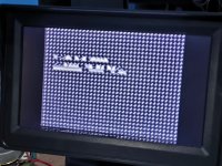
Here's how the screen looks rn, using the stock bios. This screen is black and white, just for testing purposes, so I don't know the real colors of the glitched image. Traces looks fine, will check with a multimeter later and also resolder the NEO-B1 and LSPC2-A2 chips but solder on them doesn't seems to be cold. In case I don't find the issue, I'll send it to a pro on MVS repairs.
 

Attachments

  • glitch.jpg
    glitch.jpg
    177.7 KB · Views: 17
That picture is pointing to a data issue with the 32K vram. If you can take a up close and in focus picture it maybe possible to narrow down were to look.
 
Back
Top