
You are using an out of date browser. It may not display this or other websites correctly.
You should upgrade or use an alternative browser.
You should upgrade or use an alternative browser.
My Ongoing Monitor Repair Logs
- Thread starter trashedcabs
- Start date


Agreed ^
Been enjoying this thread, and the straightforwardness of the info here.
It's also great to see repair logs of chassis that aren't usually talked about. I've got a few Neotec's that are on my workbench waiting to be repaired. Some of the info here on the various neotec chassis' you repaired is great info for when I tackle them.
Been enjoying this thread, and the straightforwardness of the info here.
It's also great to see repair logs of chassis that aren't usually talked about. I've got a few Neotec's that are on my workbench waiting to be repaired. Some of the info here on the various neotec chassis' you repaired is great info for when I tackle them.

-KT-2914: Works but can't seem to source a working flyback. If you have one DM me
Is it the same as the one in the 3414?
https://www.donberg.ie/descript/f/fsy_17a001.htm
trashedcabs
Grand Master
Yeah. I have some of the HR 46152 and they work but unfortunately HV is way too low, even with it maxed out in the extended menu, so the raster is huge.
trashedcabs
Grand Master
Sanwa PFX KW0606A
Symptom: Transformer whining, then shutdown
I had this chassis out at an event for a few hours and it was reported as broken. Found Q408 shorted, also found D425, R484, R431, Q420, and Q421 bad. Had a suspicion of a bad flyback so I powered it up without the flyback primary connected and it was now working. Reconnected the flyback pins and all those components failed again. Replaced bad flyback and all those components again to fix.
Symptom: Transformer whining, then shutdown
I had this chassis out at an event for a few hours and it was reported as broken. Found Q408 shorted, also found D425, R484, R431, Q420, and Q421 bad. Had a suspicion of a bad flyback so I powered it up without the flyback primary connected and it was now working. Reconnected the flyback pins and all those components failed again. Replaced bad flyback and all those components again to fix.

Did you try one of the replacement flybacks from tecknoservice or one 'rescued' from another chassis ?Sanwa PFX KW0606A
Symptom: Transformer whining, then shutdown
I had this chassis out at an event for a few hours and it was reported as broken. Found Q408 shorted, also found D425, R484, R431, Q420, and Q421 bad. Had a suspicion of a bad flyback so I powered it up without the flyback primary connected and it was now working. Reconnected the flyback pins and all those components failed again. Replaced bad flyback and all those components again to fix.
trashedcabs
Grand Master
I used one from another chassis that is a spare I haven't had a chance to look at yet. The teknoservice ones are way overpriced when you can get an entire PFX chassis from Xianyu for under $30.Did you try one of the replacement flybacks from tecknoservice or one 'rescued' from another chassis ?
trashedcabs
Grand Master
MS8-29
Symptom: Horizontal twitching, deflection protection being triggered randomly
I noticed if I maxed out H Subsize and the H Size pots the twitching problem went away, or if I maxed out the SPC control which is also connected to H size the problem would go away on the top and bottom. To me this indicated there's an issue in one of these circuits. Not many components in those circuits so checked every one and all tested good, so decided to revisit it later. Started working through the horizontal output section and found a cold solder joint on R546, reflowed this to fix the protection fault.
Twitching still present so kept working through the H output section. At this point since I checked everything I suspected two possible components: the EW transistor Q408 or the opamp on the pincushion board. I used freeze spray to freeze both and as soon as I hit the opamp the twitching went away. I ordered a new one and am waiting for it to arrive.
Symptom: Horizontal twitching, deflection protection being triggered randomly
I noticed if I maxed out H Subsize and the H Size pots the twitching problem went away, or if I maxed out the SPC control which is also connected to H size the problem would go away on the top and bottom. To me this indicated there's an issue in one of these circuits. Not many components in those circuits so checked every one and all tested good, so decided to revisit it later. Started working through the horizontal output section and found a cold solder joint on R546, reflowed this to fix the protection fault.
Twitching still present so kept working through the H output section. At this point since I checked everything I suspected two possible components: the EW transistor Q408 or the opamp on the pincushion board. I used freeze spray to freeze both and as soon as I hit the opamp the twitching went away. I ordered a new one and am waiting for it to arrive.

PapaBergsy
Beginner
@trashedcabs amazing work here and enjoy reading your repair notes. I have an MS2930 that starts up, gets high voltage and then 2-3 seconds later goes into shutdown. I do get HV Static on screen but strangely no relay clicks or clicking sounds. Monitoring the B+ voltage, it gets 180v at start-up then spikes up to 220-230v, then a gradual drop in voltage when shutdown kicks in. Once it has been about 20 - 30 seconds post shutdown, i do hear what I define as a single chirp sound , like a whining down somewhere in the Primary Side, not sure if that's any indication of anything and might be normal. If i remove the HV Fuse near the flyback to and fire it up again it still displays the same behaviour, so from what I've read and due to no relay clicking sounds....this has to be something on the Primary side of the board or focused to the Primary Mains section where AC Comes in. I have 114V AC coming in from the blast city PSU. I'm still learning about these classis's, but After reading your MS2930 Repair post and a few others in the forums, I am thinking could this potentially also be the Vertical IC - I am going to swap out and replace. I know there are so many reasons these things can shutdown / fail but i have nothing else to go on so willing try anything. Also Have found several caps with high esr out of spec also so thinking to do a full recap. May I ask, how did you go with your other MS2931's getting them out of shutdown ? Would be open to any advice you may have. Many Thanks!
trashedcabs
Grand Master
I had to bodge together a monitor because we have a convention coming up soon and two of the cabinets my friends recently purchased had tubes that some operator swapped out for nearly dead ones before sale. I learned quite a lot during this so figured I would share since I know it will help someone in their search.
I could not achieve full raster width when I bolted the K7400 chassis up to a good U2000 tube and yoke, which according to everyone on the internet should work with a K7400 chassis. However according to a technical bulletin from WG, there are actually certain models of U2000 and K7000 yokes that are officially supposed to require swap when retrofitted with a K7400 chassis. Additionally I got a 25" RCA TV from a local friend, and when I hooked up the K7400 to this new tube the raster did not fill the screen vertically or horizontally, despite the yoke being fairly close to the original inductance and resistance specs. There was about an inch of empty space on every side of the raster which I needed to find a solution to.
Through comparing the differences of the half dozen K7400 and K7500 chassis I had available, I quickly realized that WG themselves made lots of factory changes to match the particular tubes and yokes shipped with each monitor.
To increase the horizontal size, I referred back to the K7500 manual which describes the horizontal sweep circuit theory. Some posts online say that C722 can be changed to a lower value to increase the width, which is partially true because this is actually the S Correction cap, responsible for horizontal linearity along with the coil. Changing this will affect your linearity which in my case was already fine so I didn't want to change that. In case you ever want to adjust the linearity though, a smaller cap in C722 will shrink the middle and expand the sides. To increase raster width in the "correct" way, we can see in the theory guide that C718 and C723 are responsible for setting the retrace sweep time. Looking at 3 different K7400 chassis I have, every single one has a different value C718 ranging from 470pf to 1200pf so I increased the size of C718 to a 820pf 1.6kv cap (what I had handy) and was able to fill the screen. Try this if you have a K7400 and can't quite fill the width with your particular yoke.
Additionally, I had been trying to figure out why the image on the TV tube was so dim, despite having low hours and showing excellent on the rejuvenator. I checked R811 and R310 which are the common culprits and both were good. I replaced the filament current limiting resistor R500 on the neck board with a wire link which helped but it still felt dimmer than it should be. Turns out another factory mod WG did was changing a second filament current limiting resistor at R823--each chassis I checked had a different value ranging from 1ohm to 3ohm, and the chassis currently had a 1.6ohm installed. I replaced it with a 1.2ohm I had handy and the monitor now had excellent contrast as expected.
With a good tube, your neck board pots should all be set to about a quarter turn from minimum. Your sub contrast and contrast pots should both be set to the middle. If you need to turn either of these down more than a small amount to stop blue from bleeding to the right (blue has a fixed drive value on the K7400 which is why I am using it as a reference), then you have used too small of a resistor value and are over-driving the filament. If you need to turn these up a lot to achieve good contrast then you need to try a lower value resistor.
The moral of the story here is that not all of these chassis are identical.
Vertical size was an easy mod: The height pot on the remote board is a 200k pot that sits between R630 and R623, and decreases the size as the resistance increases. I reduced the value of R630 to 10kohm and was able to fill the screen.
I then installed the chassis for the final time and randomly lost sync. Found Q601 shorted, replaced to fix. Chassis ran for a few hours with no problems.
I could not achieve full raster width when I bolted the K7400 chassis up to a good U2000 tube and yoke, which according to everyone on the internet should work with a K7400 chassis. However according to a technical bulletin from WG, there are actually certain models of U2000 and K7000 yokes that are officially supposed to require swap when retrofitted with a K7400 chassis. Additionally I got a 25" RCA TV from a local friend, and when I hooked up the K7400 to this new tube the raster did not fill the screen vertically or horizontally, despite the yoke being fairly close to the original inductance and resistance specs. There was about an inch of empty space on every side of the raster which I needed to find a solution to.
Through comparing the differences of the half dozen K7400 and K7500 chassis I had available, I quickly realized that WG themselves made lots of factory changes to match the particular tubes and yokes shipped with each monitor.
To increase the horizontal size, I referred back to the K7500 manual which describes the horizontal sweep circuit theory. Some posts online say that C722 can be changed to a lower value to increase the width, which is partially true because this is actually the S Correction cap, responsible for horizontal linearity along with the coil. Changing this will affect your linearity which in my case was already fine so I didn't want to change that. In case you ever want to adjust the linearity though, a smaller cap in C722 will shrink the middle and expand the sides. To increase raster width in the "correct" way, we can see in the theory guide that C718 and C723 are responsible for setting the retrace sweep time. Looking at 3 different K7400 chassis I have, every single one has a different value C718 ranging from 470pf to 1200pf so I increased the size of C718 to a 820pf 1.6kv cap (what I had handy) and was able to fill the screen. Try this if you have a K7400 and can't quite fill the width with your particular yoke.
Additionally, I had been trying to figure out why the image on the TV tube was so dim, despite having low hours and showing excellent on the rejuvenator. I checked R811 and R310 which are the common culprits and both were good. I replaced the filament current limiting resistor R500 on the neck board with a wire link which helped but it still felt dimmer than it should be. Turns out another factory mod WG did was changing a second filament current limiting resistor at R823--each chassis I checked had a different value ranging from 1ohm to 3ohm, and the chassis currently had a 1.6ohm installed. I replaced it with a 1.2ohm I had handy and the monitor now had excellent contrast as expected.
With a good tube, your neck board pots should all be set to about a quarter turn from minimum. Your sub contrast and contrast pots should both be set to the middle. If you need to turn either of these down more than a small amount to stop blue from bleeding to the right (blue has a fixed drive value on the K7400 which is why I am using it as a reference), then you have used too small of a resistor value and are over-driving the filament. If you need to turn these up a lot to achieve good contrast then you need to try a lower value resistor.
The moral of the story here is that not all of these chassis are identical.
Vertical size was an easy mod: The height pot on the remote board is a 200k pot that sits between R630 and R623, and decreases the size as the resistance increases. I reduced the value of R630 to 10kohm and was able to fill the screen.
I then installed the chassis for the final time and randomly lost sync. Found Q601 shorted, replaced to fix. Chassis ran for a few hours with no problems.

trashedcabs
Grand Master
MS-2931
Symptom: Powers on, shuts off after a few seconds
Found the HOT and power mosfet Q952 blown. Replaced both and it seemed to be running but would still shut off after a few seconds which means deflection fault protection is kicking in. I could see vertical and horizontal deflection both working and all the respective feedback signals working as intended--I don't have the right probe to check HOT drain, but I can see the correct H Sense pulse from the transformer T531 so I can assume horizontal is working, and I can see the correct waveform at the vertical yoke connector so I can assume vertical is working.
At the protection opamp U451 I can see the voltage order is correct according to the manual. Pin 5 is highest at 1.5vpp, pins 3 and 6 are around 1vpp, and pin 2 is low. However, outputs pin 1 and 7 are both reading low around 0.5vpp, causing the microcontroller to send the pulse to shut down the chassis. Checked everything all the way back to the U351 MCU input pin 27 and noticed low resistance to ground compared to my other broken one. Desoldered the pin and it reads 1kohm to ground compared to the other chassis reading in the MOhm range. Replaced MCU from a parts board, monitor is now operational. U451 pins 1 and 7 are sitting high at about 1.5vpp.
Soooo... now I need a new MCU to eventually fix my parts board
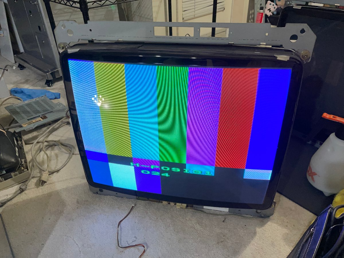
Symptom: Powers on, shuts off after a few seconds
Found the HOT and power mosfet Q952 blown. Replaced both and it seemed to be running but would still shut off after a few seconds which means deflection fault protection is kicking in. I could see vertical and horizontal deflection both working and all the respective feedback signals working as intended--I don't have the right probe to check HOT drain, but I can see the correct H Sense pulse from the transformer T531 so I can assume horizontal is working, and I can see the correct waveform at the vertical yoke connector so I can assume vertical is working.
At the protection opamp U451 I can see the voltage order is correct according to the manual. Pin 5 is highest at 1.5vpp, pins 3 and 6 are around 1vpp, and pin 2 is low. However, outputs pin 1 and 7 are both reading low around 0.5vpp, causing the microcontroller to send the pulse to shut down the chassis. Checked everything all the way back to the U351 MCU input pin 27 and noticed low resistance to ground compared to my other broken one. Desoldered the pin and it reads 1kohm to ground compared to the other chassis reading in the MOhm range. Replaced MCU from a parts board, monitor is now operational. U451 pins 1 and 7 are sitting high at about 1.5vpp.
Soooo... now I need a new MCU to eventually fix my parts board
PapaBergsy
Beginner
Amazing work and awesome you could bring this MS2931 back to life!
trashedcabs
Grand Master
Toshiba PF PD1843
Symptom: Blowing Q412, no horizontal deflection
The HOT and the HV driver Q426 were also blown. T402 is super loud and vibrating, I pulled it and the inductance readings were nearly half of a good one but I'm not sure if that actually mattered. Also noticed one leg of C419 next to it was broken off. Replaced both from a parts chassis and no change... Started investigating the area directly around Q412 again and after many many hours of hunting and pecking and isolating different sections of the circuit and comparing them to a working chassis, I found that D402 failing under load, despite testing good out of circuit. Replaced to fix.
Symptom: Blowing Q412, no horizontal deflection
The HOT and the HV driver Q426 were also blown. T402 is super loud and vibrating, I pulled it and the inductance readings were nearly half of a good one but I'm not sure if that actually mattered. Also noticed one leg of C419 next to it was broken off. Replaced both from a parts chassis and no change... Started investigating the area directly around Q412 again and after many many hours of hunting and pecking and isolating different sections of the circuit and comparing them to a working chassis, I found that D402 failing under load, despite testing good out of circuit. Replaced to fix.

cruzlink2
Grand Master
Amazing work. Would you be willing to take on a 2930? Paid work of course. My buddy's blast it stopped working,, I recapped reflowed and got neckglow but no raster/hv. Sent it away and they gave up refunded and sent it back.Toshiba PF PD1843
Symptom: Blowing Q412, no horizontal deflection
The HOT and the HV driver Q426 were also blown. T402 is super loud and vibrating, I pulled it and the inductance readings were nearly half of a good one but I'm not sure if that actually mattered. Also noticed one leg of C419 next to it was broken off. Replaced both from a parts chassis and no change... Started investigating the area directly around Q412 again and after many many hours of hunting and pecking and isolating different sections of the circuit and comparing them to a working chassis, I found that D402 failing under load, despite testing good out of circuit. Replaced to fix.
trashedcabs
Grand Master
Amazing work. Would you be willing to take on a 2930? Paid work of course. My buddy's blast it stopped working,, I recapped reflowed and got neckglow but no raster/hv. Sent it away and they gave up refunded and sent it back.
Sorry I'm way too busy to take on more repairs. My own personal queue has 50+ tasks
PapaBergsy
Beginner
I was actually about to ask the same thing. @trashedcabs really enjoy reading your repair stories on these various chassis.
@cruzlink2 , i was thinking of sending my x 2 MS2930 off to Sharp Image in Vegas, but because I am in AUS, the shipping and US Conversion $ doesn't help mainly because of my location.
I dont want to give up on my Nanao's, i have an Ali Express cart filled with parts, im tempted to give it a go and try my luck at repair.
@cruzlink2 , i was thinking of sending my x 2 MS2930 off to Sharp Image in Vegas, but because I am in AUS, the shipping and US Conversion $ doesn't help mainly because of my location.
I dont want to give up on my Nanao's, i have an Ali Express cart filled with parts, im tempted to give it a go and try my luck at repair.

nipple
Enthusiast
@PapaBergsy
Have you contacted Jomac in Perth? He is amazing with chassis, he might not work on blasts ones though? But you could ask.
He just did my ms9 chassis a few months ago and the picture is bang on!!
Cheers
Have you contacted Jomac in Perth? He is amazing with chassis, he might not work on blasts ones though? But you could ask.
He just did my ms9 chassis a few months ago and the picture is bang on!!
Cheers
PapaBergsy
Beginner
trashedcabs
Grand Master
Another Toshiba PD1843:
Symptoms: Triggering protection (monitor still running)
I had WAY more notes on this one but let me simplify it: I investigated all of the horizontal drive and HV circuits first and they seemed fine. I needed to figure out what else triggers the Murata protection module.Pin 8 being held high on the bad chassis while it's low on the good one. Of course, this is where I learn that this is an undocumented variant of the PD1843, where the protection circuit and the vertical circuit are slightly different from the other 3 I have.
Following the traces I can see the protection module is also connected to the vertical IC to shut off HV output when vertical deflection is missing so you don't burn a line in your tube. Checking the vertical IC reveals it's shorted but replacing didn't fix it. Scoping the input pins I can see the saw wave disappears at R324, and all components tested good but this was clearly the problem, so I suspected the connected D303 and after replacing it the monitor is staying alive. Had no video and realized vertical was still not working... kept tracing it further and further back and I eventually realized that F308 blew due to the shorted vertical IC and I never replaced it. Replaced to finish repair.
Symptoms: Triggering protection (monitor still running)
I had WAY more notes on this one but let me simplify it: I investigated all of the horizontal drive and HV circuits first and they seemed fine. I needed to figure out what else triggers the Murata protection module.Pin 8 being held high on the bad chassis while it's low on the good one. Of course, this is where I learn that this is an undocumented variant of the PD1843, where the protection circuit and the vertical circuit are slightly different from the other 3 I have.
Following the traces I can see the protection module is also connected to the vertical IC to shut off HV output when vertical deflection is missing so you don't burn a line in your tube. Checking the vertical IC reveals it's shorted but replacing didn't fix it. Scoping the input pins I can see the saw wave disappears at R324, and all components tested good but this was clearly the problem, so I suspected the connected D303 and after replacing it the monitor is staying alive. Had no video and realized vertical was still not working... kept tracing it further and further back and I eventually realized that F308 blew due to the shorted vertical IC and I never replaced it. Replaced to finish repair.