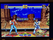
Neopass module for NeoGeo AES : the easy way to perform AES video bypass :-)

I don’t understand what you want to test or mesure in fact related to composite signal. Can you develop ?
I meant for RGB not composite.

The thing is to have your mod when 6.8k resistors disconnected like you mentioned vs when they are connected. in this case i need to measure the output rgb signals to see if they are affected in terms of level or so when i re-connect the resistors and thus composite is on.

what is the level to measure and where?
 
I meant for RGB not composite.

The thing is to have your mod when 6.8k resistors disconnected like you mentioned vs when they are connected. in this case i need to measure the output rgb signals to see if they are affected in terms of level or so when i re-connect the resistors and thus composite is on.

what is the level to measure and where?

I’m not a specialist related to signals measurements but :

On the retrosix wiki you have usefull info related to aes RGB voltage (and on YouTube they have done an excellent video related to sync and RGB measurements on AES with scope) :-)
https://www.retrosix.wiki/rgb-voltage-levels-neo-geo-aes

(you can also make a donation for us, the wiki is awesome)
 
I’m not a specialist related to signals measurements but :

On the retrosix wiki you have usefull info related to aes RGB voltage (and on YouTube they have done an excellent video related to sync and RGB measurements on AES with scope) :-)
https://www.retrosix.wiki/rgb-voltage-levels-neo-geo-aes

(you can also make a donation for us, the wiki is awesome)
Hmmm I am confused now as how you made the board and used the resistors without knowing beforehand the correct level at the output? since this is what retrosix is doing. he changed the output by varying the input resistor divider.

Or your mod is just taking the input signal as it is then passing it to output cap and correct terminating resistor? now I am looking at the board and this seems the case. If so, then it is exactly the same result as the one mentioned in the consolemods wiki above, which is the bypass mod but yours is cleaner and easier. Which means resistors can still be connected since this is the case for original bypass.

I decided to get your board regardless and try my luck with 6.8k resistors both soldered and desoldered... my scope is ready anyway. I just hoped I can get insight from here.

^
None of this is a belittling of your mod in anyway, just wanted to clear that out.
 
No problem.

The mods have been done using the « retrorgb / mmmonkey way » :-) (or the « console mods » way if you want)

So, no need for me to take time to mesure input or output (and possibly made mistake). The calcs have already been done for this for many many years.
https://retrorgb.com/aes-rgb-bypass.html

Even though it seemed good on paper, sometimes you have to take the time to really verify it.

The difficulty was to handle issues related to scalers and TV with the original bypass public mod. Many people perform this mod incorrectly and miss some components, so I need to bring an working solution to also correct this.. : missing caps on sync line.. also, adding caps on the RGB lines to remove dc offset and bring better image.

I discover the « retrosix way » later which is different and solve root cause and conception issue keeping the CXA in the chain buffering the RGB lines.

It’s not the solution I’ve selected initially as, this chip badly handle RGB signals for many many people/papers I’ve read (bring noise, blurry image..). Below a great note from Kyuusaku which explain the CXA bandwidth limitation due to the chip..
https://www.neo-geo.com/forums/index.php?threads/bad-result-from-rgb-mod.236680/

So using the CXA is a bad solution and never permit to have the best image quality possible due to the chip limitations.

Due to pcb components placement on the motherboard (which is a bit different on all revision), building an universal pcb is very complicated, as the installation need to be keep as simple as possible (for all motherboards models to install for noobs or for tech :-) Clearly, the module was originally created to save time performing the classic bypass 😂

Retrorgb done a good papers on this, my way is to adapt his solution, which is stable, clean and confirmed working solution.

using the retrosix way, I need to adapt the pcb to correct input resistors, make so test and todo later perhaps :-)

—

In any case, I hope this is clearer for you now.

There is surely room for improvement while keeping more components, but that would also mean taking risks at scale (modifying a solution is never trivial).

That said, I think the solution is now mature and stable enough to confirm that it works well in the vast majority of situations (more than 100 equipped consoles).
 
Last edited:
Do you need to cut the traces on the 3-6 for this mod or does it bypass those completely?
 
Do you need to cut the traces on the 3-6 for this mod or does it bypass those completely?
Hello 👋

with the neopass board, no need to cut anything. Just remove some components (7/8 resistors and 4 caps), place the pcb, solder it and solder the sync, that it !. The solution is quick, totally reversible and non destructive. Check in my shop on the bottom the install guide :-)

Is you have an already cutted 3-6 board, this module is also working fine once installed.
 
#neopass module USA delivery important note for our friends in the USA :thumbsup:

Shipping of parcels from France to the USA has been temporarily partially restored with a temporary workaround :shame: This will allow us to deliver to our friends in the USA again !

Unfortunately, the usual economy €5 rate for shipments per envelope (1 to 4 kits per parcel) isn't possible right now and it can only be reinstated once the full "Trump tariffs" are completely implemented in France (i don't have the complete reasons..)

I'm truly sorry for this situation, which is beyond my control, but there's no other solution available at the moment. The new temporary rate will be €36 per parcel for shipments of 1 to 100 kits (for around 500gr, if you need more, ask me)As soon as this is possible, the economy rates will be reinstated! Hang in there and stay strong!

neopass-33-34-usa.png
neopass-35-36-usa.png


Nicolas
#NeoGeo #RetroGaming #ShippingUpdate
 
Hi Nic034,

Just wanted to check with you if your board would be compatible with a 3-6 board with the csync mod below. The yellow trace was cut and the purple one is a jumper wire to enable csync. You might be more familiar with it than I am anyway :)

I did this mod on my 3-6 along with the removal of the 3 traces that caused video noise. It works fine but I think the colours are off, they feel saturated. Would your board help with that?

Thanks!
30089.jpg
 
Hi Nic034,

Just wanted to check with you if your board would be compatible with a 3-6 board with the csync mod below. The yellow trace was cut and the purple one is a jumper wire to enable csync. You might be more familiar with it than I am anyway :)

I did this mod on my 3-6 along with the removal of the 3 traces that caused video noise. It works fine but I think the colours are off, they feel saturated. Would your board help with that?

Thanks!
30089.jpg

Hello 👋 jcoelho

I will try and answer and provide additional informations

The NeoPass follows the public bypass recommendations and adjusts RGB levels to the correct ones. Great article here, thanks Bob: https://retrorgb.com/aes-rgb-bypass.html

After the RGB fix, the colors are brighter and cleaner. Additionally, if you use clean sync instead of composite sync, the result will be as you described (colors a bit saturated but great).

So, if you want a more “darker NEC-AES like image” or a “composite image feeling”, the bypass is not the way to go.

The NeoPass installation process removes composite as you did, the Jedi way 😂 (yellow trace). Just remove the sync mod you did (pink cable) and perform the NeoPass install following the NeoPass tutorial.

Official installation tutorial :
https://docs.google.com/document/d/1DW_lNX1gVnzn6eskqjlvmDjq-ONNK4JPr90uxVrRai4/edit?usp=sharing

Note : Both av port pin3/7 on 3-6 will be feed by proper sync coming from CXA encoder, corrected with additional components on the neopass.

The RGB fix already done is also compatible with neopass.

I use the « B » point on your scheme (CXA pin 11) to feed the neopass (The TTL sync « A » point don’t have the correct level for this pcb, don’t use it). After R cap, G cap, B cap and Sync cap removed, you need to remove the 6.8ko RGB « resistors and the 75o output resistors.

Then put 1mm solder balls on the holes, place the pcb and solder the points.

1777212603988.jpeg


1777212451815.jpeg


Connect the proper sync from CXA to the neopass, finished 😂

1777212660084.png


1777213109988.jpeg


Nico
 
Last edited:
Please find some pics using RGB scart or YPbPr with Retrovision HD cable (with neo addon)


Hello 👋 jcoelho

The neopass follow the public by-pass recommandations and adjust RGB level to correct one. Great article here thanks Bob : https://retrorgb.com/aes-rgb-bypass.html

After RGB fix, the color are brighter and cleaner, addirionnal if you use correct sync instead of composite sync, the result will be like you said (color a bit saturated by great).

So, I you want more « darker image nec-aes like» or « composite image feeling », the bypass is not the way.

Neopass installation process remove composite as you done, the Jedi way 😂 (yellow trace). Just remove the sync mod you done (pink cable) and perform the neopass install following the neopass tutorial.

Official installation tutorial :
https://docs.google.com/document/d/1DW_lNX1gVnzn6eskqjlvmDjq-ONNK4JPr90uxVrRai4/edit?usp=sharing

Note : Both av port pin3/7 on 3-6 will be feed by proper sync coming from CXA encoder, corrected with additional components on the neopass.

The RGB fix already done is also compatible with neopass.

I use the « B » point on your scheme (CXA pin 11) to feed the neopass (The TTL sync « A » point don’t have the correct level for this pcb, don’t use it). After R cap, G cap, B cap and Sync cap removed, you need to remove the 6.8ko RGB « resistors and the 75o output resistors.

Then put 1mm solder balls on the holes, place the pcb and solder the points.

1777212603988.jpeg


1777212451815.jpeg


Connect the proper sync from CXA to the neopass, finished 😂

1777212660084.png


1777213109988.jpeg


Nico
Understood, thanks!

I got a bit too excited and placed an order but just wanted to check...would this help with the colour balance even though I can equalize them on the Retrotink4k? I'm not sure if there's a difference between doing it on the scaler or getting a properly balanced signal from the console, is one option better than the others in terms of color balance?

Thanks again.
 
Understood, thanks!

I got a bit too excited and placed an order but just wanted to check...would this help with the colour balance even though I can equalize them on the Retrotink4k? I'm not sure if there's a difference between doing it on the scaler or getting a properly balanced signal from the console, is one option better than the others in terms of color balance?

Thanks again.

The result will be amazing man on retrotink 4k, for sure.

Please check my customer feedback with retrotink 4k + neopass
https://x.com/nic0344/status/2047735838352593227?s=46

 
Been keeping an eye on these, but shipping is still too much for my needs. But I'm not in a rush.
@retrojeff83 on X have some pieces left in US I think, contact him in behalf of me man :-)
 
Back
Top