I've seen SOP32 adapters for 5V flash ROMs on OSH Park. Then the only chips that would need the voltage regulator are the SOP 44 and you can run wires for those.
You are using an out of date browser. It may not display this or other websites correctly.
You should upgrade or use an alternative browser.
You should upgrade or use an alternative browser.
Possible to convert Seibu SPI games?
- Thread starter SwaggaJackin'
- Start date
I tried converting from senkyu(Battle balls)
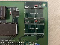
3 of OBJ Files uses by MX29L3211 with 3.3v regulator.
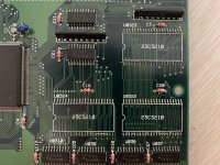
Program files uses 27c4001/27c040 and 27c1024, 27c512.
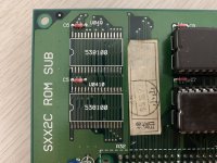
I think changed pinout (like SNES Carts) or protection/encryption in 538100 chips.
Sound (effects) is very regular.
3 of OBJ Files uses by MX29L3211 with 3.3v regulator.
Program files uses 27c4001/27c040 and 27c1024, 27c512.
- OBJ and Program files are fine. pinout is JEDEC standard.
- But, Background and sound is imperfect.
I think changed pinout (like SNES Carts) or protection/encryption in 538100 chips.
Sound (effects) is very regular.
Last edited:
I would start by double checking that you have the tile and sound roms in the correct locations, I recall that the order they were placed in was not intuitive.But, Background and sound is imperfect.
youtube.com/watch?v=1HW0t8lQMW0&feature=youtu.be
I think changed pinout (like SNES Carts) or protection/encryption in 538100 chips.
Sound (effects) is very regular.
typically if there is pin swapping it will be included in the MAME driver, I don't recall seeing any of that mentioned, though you can confirm by dumping the original chips and see how they match up and looking at the dump to see if there is any human readable text.

It has been done.Hmm are they 538100 mroms? I thought I read 538000 in the driver. Did you check the silk in the pcb after removing the originals?
Attachments

ic3b4ll
Professional
If you have a scope you can check the voltage levels on the ROM control and address lines. TTL voltage for a logic high level is far from 5V. It's likely to be within the tolerance for the flash chip. Check the datasheet.good, I will try and prepare for a conversion of my battle ballz too.. not too keen on using MX29L3211 without proper levertranslation for all affected pins, but I do got a few of them ready to go.. hmm
Output levels are the same but backwards

It's unlikely you'll have issues unless they are too low for TTL but I'd guess you won't have trouble.
Source: I read the MX29L3211 datasheet some time ago.
pacman70
Student
pacman70
Student
ic3b4ll
Professional
pacman70
Student
XtraSmiley
Legendary
Wow.
when you change sound you need to re-transfer to mobo, sound data is saved on mobo, graphics data is streamed from cart.but.. sound is imperfect now. same as before.
when you change sound you need to re-transfer to mobo, sound data is saved on mobo, graphics data is streamed from cart.
Thank you for the reply.
When I tried since first, I change only program roms. Maybe senkyu's sound transfer in mobo.
re-transfer has been a success.
Now is fine!
The only problem remaining is the 'NEW VERSION' logo.
")
I updated my Viper Phase 1 to New Version. I switched the jumper for game change, but I never saw any transfer happen. Is there some indication or progress bar that shows this happen? It’s possible I did the transfer jumper wrong.
I find the jumpers on this board confusing, mislabeled, and the manuals aren’t much better at showing the jumpers. No reference of orientation either. I can’t be the only one...

I find the jumpers on this board confusing, mislabeled, and the manuals aren’t much better at showing the jumpers. No reference of orientation either. I can’t be the only one...
ic3b4ll
Professional
@everten if nothing happened you changed the wrong jumper. There are two jumpers and a switch. The switch is in the middle of the board, is red, and controls screen flipping.
The jumpers are to the left of the jamma edge. The closest to the amplifiers controls mono/stereo.
The other is close to a pair of flash chips (very flat with tiny pins). This is the one you want to change.
There will be a countdown when you change the jumper.
WAIT UNTIL IT ENDS OR YOUR MOTHERBOARD WILL DIE.
Once complete, turn off the board and change the jumper again.
Have fun!
@ic3b4ll Not sure what you mean by tiny flat pins. They are the same jumper sizes on my V2.0 board.
I think you might have them reversed too.
Someone please verify my info. I believe the jumper orientation differs between boards too (see photos).
On board revision 2.0:
Jumpers are aligned perpendicular to JAMMA edge
JP1 (Labeled JP072) jumper is for changing games and is closest to the stereo connector CN1
JP2 (Labeled JP121) jumper is for mono/stereo
CN1 stereo connector is orange JAE connector

On boards V2.1:
Jumpers are aligned parallel to JAMMA edge
JP1 does not exist. I believe the board auto changes/loads new carts
JP2 (Labeled JP121) is for mono/stereo
CN1 stereo connector is beige Hirose connector

I think you might have them reversed too.
Someone please verify my info. I believe the jumper orientation differs between boards too (see photos).
On board revision 2.0:
Jumpers are aligned perpendicular to JAMMA edge
JP1 (Labeled JP072) jumper is for changing games and is closest to the stereo connector CN1
JP2 (Labeled JP121) jumper is for mono/stereo
CN1 stereo connector is orange JAE connector
On boards V2.1:
Jumpers are aligned parallel to JAMMA edge
JP1 does not exist. I believe the board auto changes/loads new carts
JP2 (Labeled JP121) is for mono/stereo
CN1 stereo connector is beige Hirose connector