Raizen Batrider Graphical Issue

r27blades

Student
Joined
Apr 21, 2024
Messages
91
Reaction score
49
Location
New York
Hi Everyone,

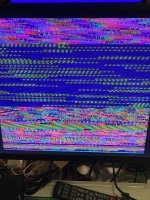
Thanks for reading and taking the time to stop by. I am trying to work through a graphical issue with my Raizing Batrider board. The game loads, and I can hear the audio. I can press buttons, and the game starts, but the graphics are garbled. I tested the voltage at the PCB, which confirmed between +5V and +5.15V. I reseated the EPROMs. Each boot cycle, I get what you see below. In testing other boards, I am not experiencing an issue like this. Has anyone seen something like this?

Thanks for your time!
 

Attachments
  • IMG_0552.jpeg
    IMG_0552.jpeg
    350.7 KB · Views: 33
Last edited:
Dump the ROMs with an EPROM programmer and see if they match MAME.

As for testing the custom, ideally you want to use a logic probe or oscilloscope to probe the Address, Data and Enable pins on the graphics EPROMs to make sure they’re getting signals from the custom correctly. I made a YouTube tutorial video that covers it a few years back.

The graphics EPROMs on Batrider are labeled rom-1, rom-2, rom-3, and rom-4
IMG_7103.jpeg

View: https://youtu.be/2PAtTIAijeA
 
Yikes. Sounds like I am in a bad spot with this one. What causes this to happen usually? It was working fine the last time I powered it on a few months ago, and the board is extremely clean.

I'll have to do some shopping to run these tests. I was hoping an eprom swap was going to solve my troubles here but by the sound of it this could be a major issue?
 
Batrider has a somewhat different setup than Bakraid.

Bakraid uses a Xilinx CPLD to drive the Text layer that is known to frequently fail. When it does, the text layer overlays garbage on top of the game. There's a discussion thread with screenshots here:

Thanks to @brandon.arnold and Coin-Op Collection, we now have full schematics for Batrider available here:
https://github.com/Coin-OpCollectio.../blob/main/Toaplan2/Raizing/RA9704/ra9704.pdf

If I'm reading the schematics correctly, the four graphics ROMs are tied directly to the GP9001 custom chip (schematic pages 8 and 9). The GP9001outputs to two TMS45160DZ DRAM chips. Page 15 of the schematics covers the Video RAM and the MACH211 CPLD & TVRMCTL custom combo which drives it and some other busses.

If you're lucky, the problem with your board might be those DRAM chips (cheap) or the GP9001 custom (can be sourced from a cheap Toaplan 2 hardware game like Ghox or Teki-Paki). If you're unlucky and your MACH211 CPLD or TVRMCTL custom failed then than those can currently only be sourced from another Batrider. It would definitely require some diagnosis time with a logic probe or scope to say for sure what your issue is.

If you leave the board powered up, does it still boot and play with bad graphics but working controls and music? Or does it freeze on the bootup screen? If you could post a video that would be helpful.

Pinging @Hatsune Mike since in addition to Brandon he has a lot of familiarity with this hardware.
 
Hi @ShootTheCore,

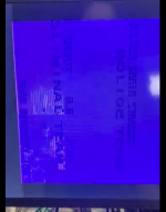
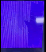
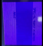
Really appreciate you sharing this and for taking this deep dive with me. The game is running behind the graphical mess and periodic purple screen. You can hear audio and blindly navigate your way into the first level. Here is a video. I feel like the graphical sequencing is random. In this recording, I have long purple-screen periods, whereas last night, when I was testing, it looked completely scrambled. I ran a test after the recording, and you could see the shape of sprites for a second before they disappeared into waves of graphical mess.

https://drive.google.com/file/d/1K5YTJi6_fKORmA3TUBPOfwI8FlCBuP9r/view?usp=drivesdk
 
Last edited:
Thank you for the video. I can see at a few points that sprites are trying to display:
Screenshot 2026-03-31 at 3.17.28 PM.pngScreenshot 2026-03-31 at 3.18.45 PM.pngScreenshot 2026-03-31 at 3.18.03 PM.png

Now this is all armchair diagnosis based on my understanding of the schematics - it's no substitute for checking the board out firsthand with diagnosis tools. Since the game is running and the sound works, then the Main CPU & Sound CPU and their associated ROMs are all functional.

@brandon.arnold 's documentation has a great writeup on how the graphics system of this hardware functions:
https://github.com/Coin-OpCollectio...lob/main/Toaplan2/Raizing/toaplan2_raizing.md

My understanding from the writeup is that the GP0001 custom handles which sprites are retrieved and where on the screen they go. It looks like the correct sprites are being retrieved and they're drawing to the correct onscreen locations, so the GP001 is presumably fine.

The TEXT layer that draws the scores and "Insert Coin" is having problems since that text isn't showing up. Since the TEXT layer draws over the top of everything else, the layer is likely glitching and covering up parts of what's drawn underneath. The TEXT layer isn't handled by the GP001 - it's written by the CPU directly into the frame buffer.

The background layers also don't seem to showing up at all.

Given those symptoms, much like Battle Bakraid, I think it's very likely that either one of the MACH1 CPLDs, MACH211 FPGAs or the TVRMCTL7 custom has failed. Replacements for the MACH1 and MACH211 components can be purchased, but they must be programmed with a bitstream before they'll function. Bitstreams are available for the equivalent parts on Battle Bakraid, but not yet for Batrider. Your board might be helpful as a donor to the folks (Hatsune Mike and Recreativos Piscis) that are working on dumping & recreating those bitstreams. If the TVRMCTL7 has failed though then the only recourse is pulilng one from a donor - it's a complex custom part and I doubt it'll be reproduced anytime soon, if ever.

One workaround you can that could get it working again for a little while is lowering the input voltage on the PCB down to around 4.55V. More details here:
https://github.com/sergiopolog/bbakraid-cplds

I recommend you reach out to Recreativos Piscis to see what he thinks can be done for it. He's on X at https://x.com/Recre_Piscis and BlueSky at https://bsky.app/profile/recreativospiscis.bsky.social
 
I will definitely reach out to Recreativos Piscis. Have you worked with him before? Just curious how engaged with the community he is.

Do we know what typically causes a failure? Is it a power issue, an EPROM issue? As with any of these boards, I spent a lot on it and would definitely want to know if I inadvertently caused a failure or if it is truly just bad luck.
 
PCBs dying on the shelf is a part of the hobby.

Lots of things cause these games to die: static, power spikes, age, moisture, etc.
 
PCBs dying on the shelf is a part of the hobby.

Lots of things cause these games to die: static, power spikes, age, moisture, etc.
That was a heartbreaking moment; hopefully, having the power on more often would reduce the chances of it happening.
 
I’m so sick of it happening. I end up with more projects these days when I fire up games.
 
I've been pretty fortunate so far in that I've had almost no sitting boards spontaneously die on me. These are my general rules of thumb of board care:

1) When not in use, store the boards standing vertically in anti-static boxes. The vertical standing will help prevent warping. The anti-static box will both protect the board and discharge any environmental static build up from dust, friction, etc.
2) When removing a board from the box, discharge any static from your body first by touching something metal. Hold the board around the edges as much as possible.
3) With your cab or SuperGun, either elevate the PCB from sitting flat with PCB feet or sit it flat on something non-conductive such as wood or cardboard.
4) When connecting the board to JAMMA, be absolutely sure the harness isn't connected upside down. Install a key (easily 3D printed) in your JAMMA connector that matches the notch present in most boards.
5) Before powering on the board for the first time, adjust the arcade PSU 5V trim pot down. Power on, check the offset from 5.0V, power down and readjust. Only adjust the 5.0V trim with the power on if you're within 0.1V range of your target. You always want to start below 5.0V and move up rather than starting high and risk overvolting the board. Get as close to 5.0V as you can but understand that fluctuation will happen as the board processes the game data. If you don't have a voltmeter in your JAMMA path, get one ASAP like the @RGB Dual Voltmeter or RiddledTV Passthrough Tester.
6) As much as possible, remove batteries from boards. Retaining high scores isn't worth the risk of battery acid leaking and ruining your board.
7) Recap any boards with the original SMD capacitors - they almost always leak. Recap any boards with bulging or leaking through-hole capacitors.
 
I'm quite curious how this board is doing now. Any updates @r27blades?
Hi @Sinosphere,

After getting the great advice ShootTheCore shared, I spent about a week looking up any other threads, articles, or anything on Google to learn as much as I could. I couldn't find much.

There is a repair shop, 1Up Restorations, not far from me in NY. George (who is the owner) is a great guy, and I have worked with him in the past. We spoke about my board, and he was willing to take a look and see what can be done. While he is more than capable of doing the physical work, assuming it is not the dreaded custom issue, he is skeptical of what can be done until he digs in. The board is with him now. I dropped it off last week, and we spent some time just sharing notes.

On my end, I have shared all the great information shared here, and I am just looking to see who else I can put him in touch with.

Really appreciate everyone's support and help! I will keep this thread going with updates as they come in.
 
Last edited:
Back
Top