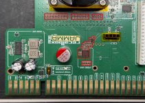
FS RecalBox Video Upgrade,

For Sale

SnakeGrunger

Professional
Joined
Nov 25, 2016
Messages
210
Reaction score
583
Location
California
Hello,
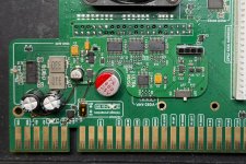
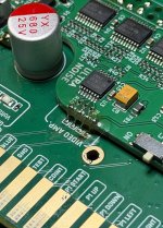
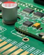
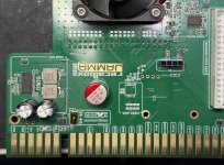
If anyone is interested, I have designed a video upgrade circuit for the RecalBox JAMMA adapter.
The original was very noisy as it pulled RGB data straight from the GPIO, which can be fine, but those signals aren't properly regulated for analog output.
I have made a brand new circuit using their own +5V and +3V3 regulation for buffering and amplifying, giving what arguably could be the best and most stable signals.
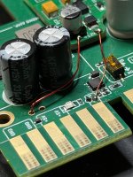
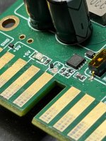
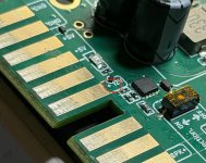
Installation isn't very difficult, simply remove all the passives for the RGB output and drop this over the GPIO pins. Hook up +12V and GND close to the jamma edge, and connect RGBs back down to the RecalBox board.

There's also a little switch for low pass filtering ON or OFF, but .. given how clean the source is now, probably not needed.

I have 8 available, selling for 40$ shipped in US (15$ more if overseas) if anyone is interested in upgrading their experience!

Will provide quick install guide very soon.
 

Attachments
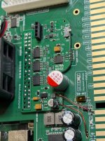
  • IMG_5914.JPEG
    IMG_5914.JPEG
    236.4 KB · Views: 242
Last edited:
are there any screenshots of before and after of the noise improvements
 
Last edited:
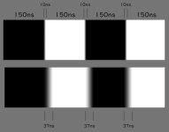
@Samurai_j I noticed two things using an oscilloscope. On the same game, real board vs recalbox, I measured the time it took for a pixel to go from black to white (slew rate). One pixel on a 15kHz screen is roughly 150 nanoseconds. On the recalbox it was about 38ns from the GPIO pins, as opposed to 10ns on real hardware. You can see the difference on this screenshot. The buffers I used take care of this issue.

Secondly, the noise can be seen on my scope as well, here is a capture of the output from the Recalbox, we can see not only spikes of noise in the signal, but that the voltage is jumping around. Again, the pi being all digital, this type of noise is within specs and will trigger 0s and 1s no problem, but for analog it is not ideal and what we see on the scope, we will see on the screen too.

View: https://youtu.be/kNLS7HJsqLs

To mitigate that, I have added TWO separate regulators to the circuit, 3V3 that powers the buffers only, and 5V that powers the video amp, for maximum stability.
 

Attachments

  • 1775244319882.png
    1775244319882.png
    86.1 KB · Views: 38
Last edited:
OK! Installation pictures.

STEP1: Look at PCB. Know which parts to remove.
STEP2: Remove the video DAC circuitry. If you use hot air, I would wet all the solder joints with leaded solder first, pour some flux, and barricade the neighboring plastic parts with kapton tape or aluminum foil. Tack down recalbox circuit on top of the pins and leave iron on top of openings with plenty of flux and some time to make sure it wets all the way down the pin.
STEP3: Find +12V source near jamma edge (PIN6)
STEP4: Scratch off tiny bit of mask with blade, watching out not to damage the little diode or stepping out of bounds.
STEP5: Connect +12V and GND near JAMMA edge to new circuit. Check make sure there is no short with ground or tiny neighboring components!
STEP6: Tack some small wires at the base of the RGBs pins and cut to length (easier)
STEP7: Bend over top of the wires and solder down to new circuit.
STEP8: Ready to play!

Potential issues :
NO SYNC!... Pins 3 and 5 fom the Pi GPIO not connected correctly. You need to let plenty of solder melt and go down the via for it to contact pin.
NO SYNC STILL!... Check if you have +12V coming into "1" pin here, and you get 5.1V coming out of "2". If no +12V coming in there won't be power to the sync combiner logic.

1775632710958.png


COLORS WRONG!.... Again, missed pin contacts on the GPIO. You can check with a multimeter in contact mode, touch both sides, with Pi inserted, if contact is made all the way through. You should find opens if you have color issues.
 

Attachments

  • STEP8.jpg
    STEP8.jpg
    255.1 KB · Views: 97
  • STEP7.jpg
    STEP7.jpg
    232.6 KB · Views: 88
  • STEP6.jpg
    STEP6.jpg
    193.8 KB · Views: 87
  • STEP5.jpg
    STEP5.jpg
    193 KB · Views: 79
  • STEP4.jpg
    STEP4.jpg
    176.6 KB · Views: 82
  • STEP3.jpg
    STEP3.jpg
    158.2 KB · Views: 83
  • STEP2.jpg
    STEP2.jpg
    272.1 KB · Views: 89
  • STEP1.jpg
    STEP1.jpg
    271.1 KB · Views: 97
Last edited:
Buy with confidence on this one if more come up for sale.

It 100% addressed the noise issues I kept seeing with the recalcbox on all my cabs. Things now look amazing and crisp.

Install itself was not so bad outside of me messing up step 7.

Thanks @SnakeGrunger for this awesome mod!
 
Back
Top