What's new

ArcadeMachinist

Professional
Joined
Nov 30, 2018
Messages
159
Reaction score
359
Location
Florida
I would be posting some pictures of my current restoration project.
SEGA G-Loc Deluxe flight simulator - R360's smaller brother.

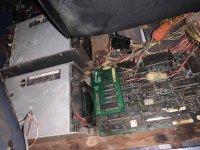
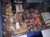
Got this machine with completly dead lower part, looks like sometime ago it was stored outside (rust and corrosion) and it was home for a rat family too (major parts of wiring eaten away).

As of now it is playable, but no motion.
One of it's two motor driver boards needs new (custom) transformer.
Also some cosmetics, like seat plastic (fibegass now) needs more sanding and paint.

It was taken apart completly for restoration (and to fit my door).

2021-01-05 23.21.50.jpg125789641_373472740546606_1694790361935573234_n.jpg125789641_1000681237103262_6928402733710555386_n.jpg
 
Last edited:
Damn you don’t see these often! Verry nice

Keep up the good work . Can’t wait to see it al finished :thumbsup:
 
Joysticks and new lights:

Main joystick missile button (square orange) was replaced with a slightly bigger one, which looks exactly as original, just few mm bigger.
Original is still produced and available from the manufacturer, but only in Japan and was never exported, except in SEGA button replacement kits.

Pinion gear is from the throttle joystick assembly.
Had to repurpose RC helicopter part to match SEGA 601-5410, as it is not currently available.
For future reference:
Throttle gear is: M0.6, T15, 6mm shaft.
Replacement orange button: UB15KKW015D-DD


joystick1.jpgjoystick2.jpgjoystick3.jpg2021-01-05 23.43.03.jpgbacklight1.jpg009.jpg
 
Last edited:
Now the main trouble (common for this machine) is: dead motor driver boards, and glitching motor control logic PCB, as turned out later.
There are very detailed diagnostics and repair instructions for these boards available on french GameOver forum.
I was able to fix one of the driver boards and the logic board by swapping dead parts with brand new ones.
Second driver board is still dead, because it needs new L2 transformer, which was custom made for SEGA.
Thanks to fellow arcade enthusiast from Denmark these were also analyzed and reproduced.

Now just waiting for one to arrive.

Motor board has a voltage multiplier circuit and drives it's motor with PWM pulses, with ~335 volts, if it is 100% duty (normally it is never doing anything close to that).
When logic board was glitching it actually was sending 100% to the motor driver board and the cabin was trying to fly away from the base.


2021-01-05 23.53.34.jpg2021-01-05 23.54.30.jpg2021-01-05 23.54.24.jpg
 
Last edited:
As of today - it needs the seat to be completed and motor driver board issue fixed.
May be CRT should be looked into as well. When the cabin moves (it does on 1 motor during startup check sequence) - the image really jumps across the screen.
Not sure if it is something mechanical with the tube/yoke/connections or interference from the motor circuits.

If I run several motion tests in a row - monitor would be showing weird picture like on the 4th photo.
After sometime it would go back to normal by itself. Any ideas? :)
 

Attachments

  • 2021-01-05 23.59.11.jpg
    2021-01-05 23.59.11.jpg
    164 KB · Views: 252
  • 2021-01-05 23.59.04.jpg
    2021-01-05 23.59.04.jpg
    182.4 KB · Views: 178
  • 2021-01-05 23.58.59.jpg
    2021-01-05 23.58.59.jpg
    191.5 KB · Views: 237
  • 2021-01-06 00.02.30.jpg
    2021-01-06 00.02.30.jpg
    176.7 KB · Views: 183
Last edited:
Wow, very nice work, @ArcadeMachinist. I can't see there being many of these left. Kudos to you.

May be CRT should be looked into as well. When the cabin moves (it does on 1 motor during startup check sequence) - the image really jumps across the screen.

Likely cracked solder joints. These moving cabs are hard on the monitors.
 
This is a full project that is so rewarding because you touch so many aspects !! Congratulations!!
that bottom full of boards is beautifull !! 8| Very similar to a full size PowerDrift I saw in november... and left there!
 
Just a small update how it is going.

Still need to fix one motorboard.
May be someone can tell me why, when connected to MAINS, there is 0v after R21b, when it should be normally 3v.
Before R21a = 337v
Between R21a and R21b = 168v
After R21b = 0v (normal working board has 3v here).

Image shows different voltages, when R21b is removed and 3v lab PSU is connected instead.
I have replaced all zeners, resistors, Q1
Q2 is not replaced, but transistor tester shows it is fine.
If I remove R22 - then 3v is back after R21b.
 

Attachments

  • seat5.jpg
    seat5.jpg
    151.3 KB · Views: 192
  • Screen Shot 2021-01-17 at 5.25.32 PM.png
    Screen Shot 2021-01-17 at 5.25.32 PM.png
    995.9 KB · Views: 188
Where you able to get it all restored and back together! Thats some serious work going there.
 
Where you able to get it all restored and back together! Thats some serious work going there.
One of the motor boards still needs work.
Since last post here I've managed to burn my working board too, but then restored it.
The board that originally didn't work is still dead.
But I'm approaching the fix.
Now have better understanding how it works, completly reproduced PCB, so all the stuff can be moved onto the new board without corrosion and dead traces.

20220811233409-ArcadeMachinist-GLOC_MotorBoard_Render_2.jpeg2022-08-19 00.57.49.jpg
I have managed to get correct 2.7v on Q1 gate, and L2 transformer (which is repro too) did produce correct voltage on 5-3 coil (7.1v)
However some seconds later Q1 overheated and smoked. Tester says it is still ok, and it even works in low voltage LED driving circuit, but I suppose it leaks high voltage.
Waiting for replacement to arrive, it is pretty rare obsolete 2SK1535, with 3V gate threshold voltage.
At the time of the experiment TR1 was removed. Not sure how it might have affected the circuit, except it runs on half of the voltage (164v instead of 330v).

Here is a schematic of the problem part (from another forum, where everyone seems to be dead):
01-High-Voltage-Input.gif.jpg
02-High-Voltage-to-Transformer.png.jpg

I wish there were some Electric Engineers to speak with.
Low voltage part is verified to work, including all the logic.

PCB repro, for those who might find this thread and own dead boards: https://github.com/ArcadeMachinist/GLoc-Motor-PCB/tree/main/kicad-reproduction


Updating my previous post about PCB not putting 100% pwm duty:
Actually when the game is active each board drives the motor always at 100% duty.
As it does not have any breaks and it needs to hold the moving part with the player's weight - it always does 100% pwm duty and then alternates between up/down every 32μs. 32μs up, 32μs down. 64μs full cycle.
This holds the motor in place.
When the cab goes up on startup, I'm getting 37.5μs "up", 26.5μs "down", so around 58.5% up.
When it slowly returns back down, it is 30.2μs "up", 33.8μs "down".
Basically it is 15Khz (15625Hz) pwm, but it drives "direction", not "enable" pin.
 
Last edited:
I just picked one up as well. This will be the largest project I have ever done. I believe looking at your photos I have all the parts except for a monitor which I plan to convert this to an lcd. I found it interesting that my power supply transformer on the bottom left is different than yours. It is big an black with the power cord coming out of it. Once I get it taken apart and power washed I will take more photos.
 

Attachments

  • 20230310_191510.jpg
    20230310_191510.jpg
    180.9 KB · Views: 103
  • 20230310_191454.jpg
    20230310_191454.jpg
    188.3 KB · Views: 101
  • 20230324_174917.jpg
    20230324_174917.jpg
    244.3 KB · Views: 97
After a long pause I'm back into this project.
No one, even "professional" paid services, was able to restore or recreate my 2nd motor drive board.
So, I guess, it was time to move on.

Meet new, closed loop hybrid servo powered G-Loc!

It turns out original G-Loc motors (SEGA 16611) are actually NEMA34 complaint.
So these modern motors are a drop-in replacement.

2024-03-15 22.15.21.jpg

I did use the servos, so I won't have to use SEGA's approach of constantly changing direction each N ms, just to hold motor in place.
Neither I wanted to use an external break. Servos hold the position by design, with enough torque.

I was able to decode main CPU to motion controller PCB (839-0341) comms and vice versa.
I would be using ATMega 2560 with a DIN rail breakout (just because I have it), and later would design a drop-in replacement PCB.
 
This thread makes me want a powerdrift deluxe so bad
 
After a long pause I'm back into this project.
No one, even "professional" paid services, was able to restore or recreate my 2nd motor drive board.
So, I guess, it was time to move on.

Meet new, closed loop hybrid servo powered G-Loc!

It turns out original G-Loc motors (SEGA 16611) are actually NEMA34 complaint.
So these modern motors are a drop-in replacement.

2024-03-15 22.15.21.jpg

I did use the servos, so I won't have to use SEGA's approach of constantly changing direction each N ms, just to hold motor in place.
Neither I wanted to use an external break. Servos hold the position by design, with enough torque.

I was able to decode main CPU to motion controller PCB (839-0341) comms and vice versa.
I would be using ATMega 2560 with a DIN rail breakout (just because I have it), and later would design a drop-in replacement PCB.
Awesome work. I had been watching the progress of the repro boards on gamoover as I have one of these shame it hasn't been figured out yet.

In your demo it looks like they're going a little slower than the stock speed? have you had them cranked up as I know steppers can get quite noisy. I started doing something similar with my punch mania (swapping the stock motors for steppers).
 
Back
Top