System 32 Golden Axe 2 Conversion graphic issue and Heat Sink Q

r27blades

Student
Joined
Apr 21, 2024
Messages
91
Reaction score
49
Location
New York
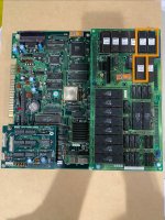
Hope you are doing well my friends! I noticed something with my Golden Axe 2 board and was hoping to ask for your guidance.

I initially noticed some graphical anomalies showing up when the game was running. Vertical lines that looked like banding.

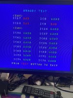
I ran the memory check in the test menu and saw 3 “bad” ROMs. I took them out and cleaned them with ISO and noticed I still received the error message. I had a friend burn me a set of ROMs. He runs a EEPROM service so I knew I wouldn’t have an issue.

Turns out with the 3 replacement EEPROMs in the board would not display. Put the originals back i was able to get the game running and jump into the menu. Sure enough same 3 failures.

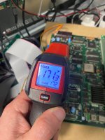
At this point I had the board powered 3-4 times during a 20 minute window. I accidentally touched the heat sync while I was adjusting the audio dial and it was HOT. Not sure how hot it is suppose to get but when I did a quick reading it was 170-185 degrees Fahrenheit. My gut was telling me that might be a little too high and I should reach out to the community.

I attached some photos. I have voltage sitting at +5.07V on the PCB side.

Thanks for your time as always.
 

Attachments

  • IMG_0535.jpeg
    IMG_0535.jpeg
    348.1 KB · Views: 37
  • IMG_0531.jpeg
    IMG_0531.jpeg
    420 KB · Views: 36
  • IMG_0381.jpeg
    IMG_0381.jpeg
    545.4 KB · Views: 36
The audio amp running hot and the graphic anomalies are two different issues.

I had a friend burn me a set of ROMs. He runs a EEPROM service so I knew I wouldn’t have an issue.

Turns out with the 3 replacement EEPROMs in the board would not display.

Your replacement eproms were either burned on the wrong chip type or have the wrong data on them.

As for the amp and heatsink, what is your setup and how is your audio wired on it?
 
Hi @nem,

Appreciate you jumping in and looking to help. Here is some updated information from my testing and discussions with the previous owner.

Your replacement eproms were either burned on the wrong chip type or have the wrong data on them.
After speaking with the seller, I learned that the board is a conversion. It is running a modified program to disable the protection module (prone to failures). The individual who performed the conversion (not the seller) didn't consider it important to correct the CRC checksum of each EPROM, so the system wouldn't detect the error.

He suggested reseating the ROM board to see if that eliminates the graphical issue. I tried it last night, and it did. Between last night and today 9 different tests boots and no vertical lines.

As for the amp and heatsink, what is your setup and how is your audio wired on it?
This is where I think I will need the most help. Unless I am misunderstanding, the 4-pin connection by the heat sink is the board's stereo out. L + L- R- R+. I am connected to those back to my switcher. I am using a RiddledTV switcher. From the switcher, I am connecting to this amp via its 3.5mm barrel jack. My assumption was that this would be fine since I am not tying the PCB amp connection to another amp, but rather setting the PCB amp's output to the switcher board, and the volume dial at the cabinet's amp would receive the signal from the switcher. I suppose it could still be a direct load issue.

Would that still be true when I am going over the Jamma edge for the audio and not the stereo for the PCB? During testing, both connections spiked to 185-200 when the board was powered on. With the Jamma only, it would drop to around 100, but with the stereo connection, it would drop to ~170.

[Quick Update]
I have 2 Konami boards set up the exact same way. I let both run for 10 minutes, and neither saw their heat sink exceed 86 degrees. Not saying that would rule out a load issue, just sharing an observation.
 
Last edited:
Have you tried connecting Golden Axe straight to the amp without the switcher in between?
 
Take a look at the mame driver for this game, and deduct: You're running hacked code on a conversion, so the main cpu roms might have a bad checksum since they are modified. Those you can ignore.

If you dropped in original program roms, the board won't boat. Put the old modified hacked main cpu roms back in the board, but keep the new gfx rom.
 
After speaking with the seller, I learned that the board is a conversion.

When you bought the board you weren't told that it is a conversion?

I only now noticed the stickers and how eeproms have been used where you would normally have mask roms.
 
I am using a RiddledTV switcher. From the switcher
Check to see if the Audio Negative pin on the JAMMA edge is being grounded by your Riddled TV switcher.
it should NOT be grounded but I've seen many switchers and super-guns and other interface devices make this mistake.

Some JAMMA PCBs have "balanced" audio output in which the Audio Negative pin is an inverted wave form from the Audio Positive pin.
Some JAMMA PCBs have "unbalanced" audio output in which the Audio Negative pin is a ground.

if you're running a normal JAMMA cab then these audio pins are going directly to a speaker and either configuration works fine.
but if you're modifying the signal you MUST treat all of them like they're "balanced" outputs because if you intentionally ground the audio negative an a JAMMA board that has balanced audio you're essentially causing a short, and that short generally expresses itself internally on the audio amp causing it to overheat.
 
Where did I say that?

The audio output on the CND connector is line level. It doesn't even go through the amp on the PCB. There's something weird going on with the wiring to the switcher.

I assume from this post:

With the Jamma only, it would drop to around 100

That jamma audio alone (with nothing plugged into CND) is working fine, right? 100 fahrenheit is 38 celcius, that sounds about what I would expect it to be.
 
Hi Nem,

Thanks for the reply. Apologies, I was replying and reviewing notes. I meant that I had read earlier that it is a balance issue to go from a PCB amp directly into another. Here is what I learned. This also touches on what @twistedsymphony asked me to confirm.

I reached out to Jim from RiddledTV, and he confirmed that his switcher does not ground out any of the 4 audio pins. He did say the 4 audio pins on the Jamma GBI are directly connected to the normal Jamma audio pins on the Jamma edge connector. Not sure if that would increase resistance or have a direct impact, but I moved forward with Nem's test, connecting the stereo out to my cabinet amp.

I let the game run for 15 minutes; at no point did my temperature readout exceed 75 degrees Fahrenheit. It was warm but not hot to the touch. I couldn't find much written about temp level and PCB heat sink expectations, but this seems to point to an issue with how the switcher, or the switcher and the amp together, interacts with the 4-pin port.

What do you all think?
 
How are you wiring the stereo outputs from your boards into the switcher? Like where are connecting them to?

Unless you have some add-on board on it that I don't know about, the standard RiddledTV switcher has no connections for line level audio.
 
Got it, here is my breakdown of signal flow with part links.

Routing into Switcher:
PCB Amp 4 pins > EZ Jamma Gameboard Interface > EZ8 Switcher

Routing out of Switcher:
EZ8 Switcher speaker 4 Pin > Stereo to 3.5mm adapter > Dayton Audio KAB-2150 Amp

Here is a diagram of the Switcher board and connection overview.
https://riddledtv.com/EZ8WaySwitcher_ConnectionDiagram.pdf
 
Last edited:
You're tying the line level audio into the PCB's jamma speaker output. That's definitely going to cause an issue.

Put tape over the audio pins on the edge connector of the PCB and it will work correctly. Do it for the other boards too (I assume they're all wired for stereo?).
 
Back
Top