
You are using an out of date browser. It may not display this or other websites correctly.
You should upgrade or use an alternative browser.
You should upgrade or use an alternative browser.
Taito F3 Single board conversion COMPLETE GUIDE
- Thread starter Tailsnic Retroworks
- Start date


Tailsnic Retroworks
Champion
I'm afraid Taito F2 is more complicated. There is no Taito F2 standard format, much games have different customs and requeriments. Only Taito F2 known conversions are Football Champ/Eurochamp 92 to Dead Connection, and the "theorical" Drift Out to Pu-Li-Ru-La.Agree. Would love to see something similar for f2
Last edited:
Tailsnic Retroworks
Champion
The Dead Connection conversion is full discovered and public. The problem is because of the customs in that board, there isn't any other game you can convert it.Not that its hard to find but lmk if you want a football champ to experiment onid be happy to donate one to the cause.

1credit
Professional
Just got hold of 3 taito cup finals white board . 
This is epic for me thank you
. This is epic for me
thank you
Tailsnic Retroworks
Champion
You're welcomeJust got hold of 3 taito cup finals white board
This is epic for me
1credit
Professional
Will be great try this convert a good challengeYou're welcome
For me but so comprehensively well explained I feel I can have a crack at this one ! Your hard work is most appreciated very big thank you …
Tailsnic Retroworks
Champion
I began not knowing nothing as you, asking where I could but with no results. So I made myself the way upWill be great try this convert a good challenge
For me but so comprehensively well explained I feel I can have a crack at this one ! Your hard work is most appreciated very big thank you …
Tailsnic Retroworks
Champion
Added an extra fix needed related to D29-17 PAL on this page: https://www.arcade-projects.com/thr...d-conversion-complete-guide.31156/post-436646
1credit
Professional
I know less than nothing ..I began not knowing nothing as you, asking where I could but with no results. So I made myself the way up
But I have this pcb …
And I like your directions I can follow them !


I have 3 taito footy f3 singles
So I will have a go as son as I get time!

First of all, thanks for a very detailed guide, I took a shot at converting Taito Cup Finals to Darius Gaiden over the past couple of days, it definitely made me better with using a manual solder pump towards the end of it due to having to desolder all these mask roms 
However, so far it doesn't work for me - the board is getting into some sort of boot loop, it flashes random colours and resets itself after a couple of seconds. I strongly suspect this is something to do with the CPU EPROMS or the GAL - I swapped them back for original Cup Finals mask roms and PAL I desoldered, and the board still boots fine (with garbled graphics because I left the Darius ones in but at least it does something now).
Any idea what to check or what to try differently? Some thoughts I have:
- the guide keeps referring to D66-12 GAL, but the attached ZIP has D69-12 instead, is it just a typo somewhere or does the archive really have the wrong GAL? that would be an easy fix if that's all it is
- maybe it's some GAL/PAL incompatibility? I didn't look into it too deeply, for 20V8's my chips just say "GAL20V8-25LNC", and for 16V8 I have new Atmels "F16V8BQL-15PU" (you can see both on the photos), does it matter which one you're using exactly? I certainly didn't research any compatibility or anything like that.
- the board seems to behave exactly the same when no CPU EPROMS are inserted at all, which makes me suspect that GAL even more
- I left the 3 remaining Cup Finals mask roms in since Darius doesn't use them, but I doubt it matters?
- don't mind the brown wires on the photos, these are the jumpers I had to add because I did actually damage some traces when desoldering chips, at least at first, so I had to add them instead - but I did verify that I have a socketed board with Cup Finals mask roms and PALs working before cutting any traces or adding more jumpers (for the ones intended for conversion I used gray jumpers)
- I did notice just after uploading that one leg on D87-08 didn't insert properly I reinserted it correctly though and unsurprisingly it didn't change anything (since this is a graphics rom from what I understand)
Photos:
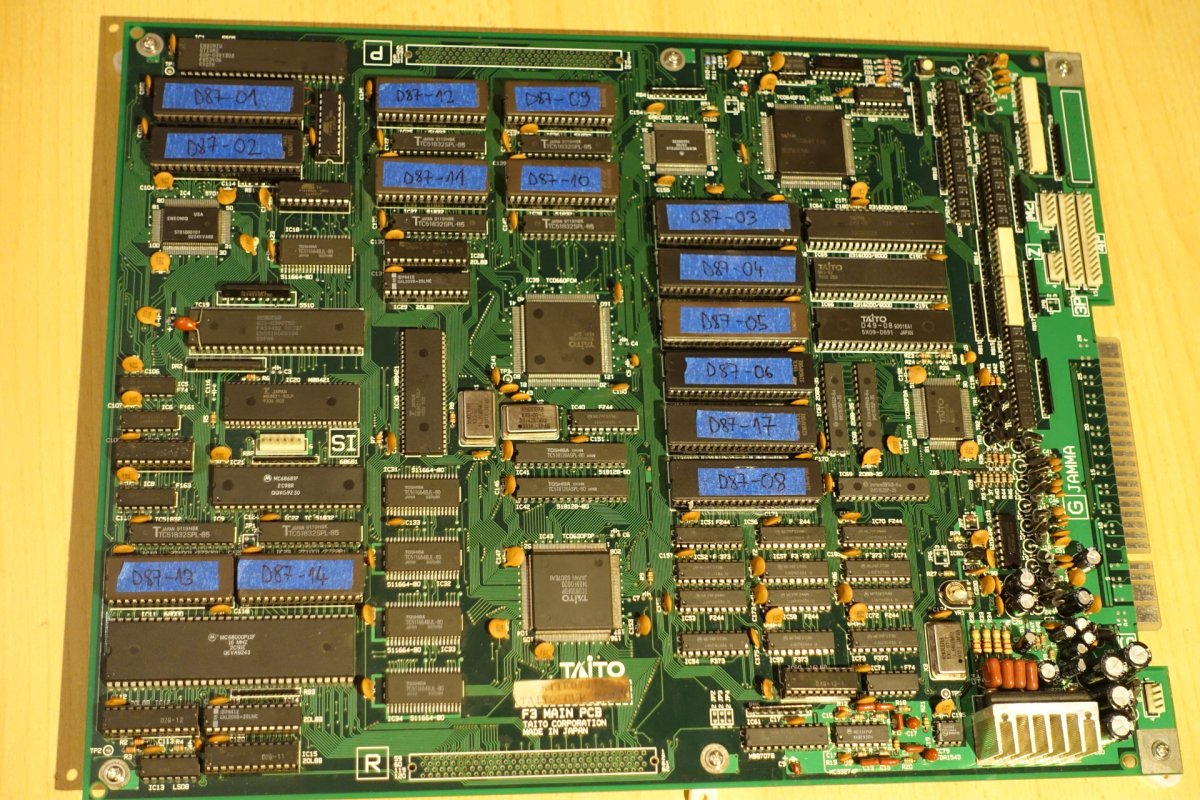
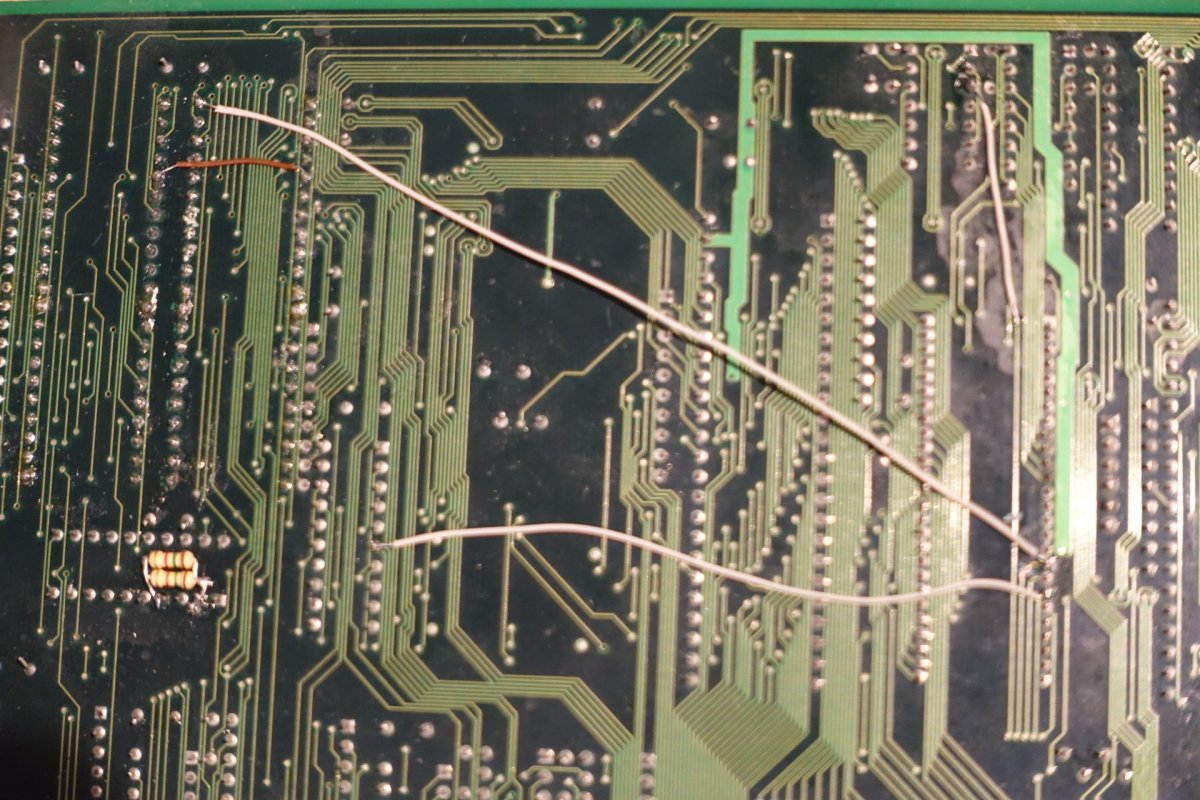
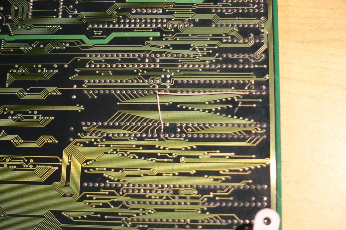
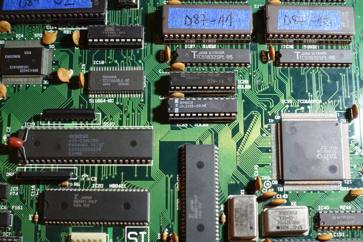
However, so far it doesn't work for me - the board is getting into some sort of boot loop, it flashes random colours and resets itself after a couple of seconds. I strongly suspect this is something to do with the CPU EPROMS or the GAL - I swapped them back for original Cup Finals mask roms and PAL I desoldered, and the board still boots fine (with garbled graphics because I left the Darius ones in but at least it does something now).
Any idea what to check or what to try differently? Some thoughts I have:
- the guide keeps referring to D66-12 GAL, but the attached ZIP has D69-12 instead, is it just a typo somewhere or does the archive really have the wrong GAL? that would be an easy fix if that's all it is
- maybe it's some GAL/PAL incompatibility? I didn't look into it too deeply, for 20V8's my chips just say "GAL20V8-25LNC", and for 16V8 I have new Atmels "F16V8BQL-15PU" (you can see both on the photos), does it matter which one you're using exactly? I certainly didn't research any compatibility or anything like that.
- the board seems to behave exactly the same when no CPU EPROMS are inserted at all, which makes me suspect that GAL even more
- I left the 3 remaining Cup Finals mask roms in since Darius doesn't use them, but I doubt it matters?
- don't mind the brown wires on the photos, these are the jumpers I had to add because I did actually damage some traces when desoldering chips, at least at first, so I had to add them instead - but I did verify that I have a socketed board with Cup Finals mask roms and PALs working before cutting any traces or adding more jumpers (for the ones intended for conversion I used gray jumpers)
- I did notice just after uploading that one leg on D87-08 didn't insert properly
I reinserted it correctly though and unsurprisingly it didn't change anything (since this is a graphics rom from what I understand)Photos:
Last edited:
Tailsnic Retroworks
Champion
First of all, thanks for a very detailed guide, I took a shot at converting Taito Cup Finals to Darius Gaiden over the past couple of days, it definitely made me better with using a manual solder pump towards the end of it due to having to desolder all these mask roms
However, so far it doesn't work for me - the board is getting into some sort of boot loop, it flashes random colours and resets itself after a couple of seconds. I strongly suspect this is something to do with the CPU EPROMS or the GAL - I swapped them back for original Cup Finals mask roms and PAL I desoldered, and the board still boots fine (with garbled graphics because I left the Darius ones in but at least it does something now).
Any idea what to check or what to try differently? Some thoughts I have:
- the guide keeps referring to D66-12 GAL, but the attached ZIP has D69-12 instead, is it just a typo somewhere or does the archive really have the wrong GAL? that would be an easy fix if that's all it is
- maybe it's some GAL/PAL incompatibility? I didn't look into it too deeply, for 20V8's my chips just say "GAL20V8-25LNC", and for 16V8 I have new Atmels "F16V8BQL-15PU" (you can see both on the photos), does it matter which one you're using exactly? I certainly didn't research any compatibility or anything like that.
- the board seems to behave exactly the same when no CPU EPROMS are inserted at all, which makes me suspect that GAL even more
- I left the 3 remaining Cup Finals mask roms in since Darius doesn't use them, but I doubt it matters?
- don't mind the brown wires on the photos, these are the jumpers I had to add because I did actually damage some traces when desoldering chips, at least at first, so I had to add them instead - but I did verify that I have a socketed board with Cup Finals mask roms and PALs working before cutting any traces or adding more jumpers (for the ones intended for conversion I used gray jumpers)
- I did notice just after uploading that one leg on D87-08 didn't insert properly
Photos:
D69-12, typo error, my bad. You need that GAL for Darius Gaiden to boot.
Alright, after attempting a very scientific method of "trying random shit" but focused on that GAL I discovered that I can make it boot if I pick a different device in the software for my T48 programmer, for whatever reason "GAL20V8" doesn't do anything, but "GAL20V8A" and other letters seem to work (and I got sound working after reprogramming that other 20V8 GAL so I'm pretty sure that was at least part of the issue). It still seems prone to resetting though and I have some vertical lines across the screens that disappear if I push on the board with my finger (no matter where), but this may be something to do with sockets and stuff... I'll try to reaseat them or something and see if it makes it better, but I'm definitely getting closer now!
Well, the reset issue seems to have resolved itself (maybe I reseated the GALs better), but frustratingly, I still have vertical lines across the background elements unless I push on the board around the graphics EPROMs.
I spent hours trying to track it down at this point, I don't think it's sockets themselves (I can kinda reproduce the touch-sensitive vertical bars even without any EPROMs in the sockets, except it of course reads random garbage and not data but I can still see them), so probably a bad solder joint? I redid all that look suspect but some still do because the solder pads didn't end up that great after desoldering in some cases. Trying to locate any break with a multimeter is tricky, very hard to tell if you're reproducing the effect of pushing on a board or you just don't have a good contact with your leads.
I even resorted to bending one leg out of the socket and resetting the game to see if now I have permanent vertical bars (checking a different leg each time), but I broke off some legs this way and wasted 2 EPROMS so I stopped that before I break any more - nevertheless I kinda got a partial result this way from the output line Q7 on EPROM IC50, but not quite (Taito logo has similar bars in the same place that are permanent, but they're still there and still touch-dependent on in-game background, so I'm not convinced it's the culprit). All connections from this point on that I could find seemed fine, and I even blindly jumpered some to make sure it's not this pin, but no luck.
I won't be able to work on this board for a while so I guess I'll just give up for now, but I'll accept any ideas of what to check. Some sort of schematics of the connections from the graphic EPROMS to the rest of the board would be best but it probably doesn't exist (I couldn't find it)?
Anyway, at this point this problem likely has nothing to do with the conversion process itself, other than this graphical issue the game seems to work flawlessly so far, so thanks a lot for the detailed guide! (there still is one instance of calling the GAL "D66-12" in the header of the "CPU EPROMS SECTIONS" table, might be good to fix that).

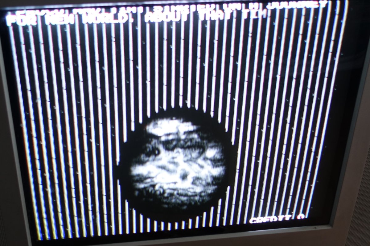
I spent hours trying to track it down at this point, I don't think it's sockets themselves (I can kinda reproduce the touch-sensitive vertical bars even without any EPROMs in the sockets, except it of course reads random garbage and not data but I can still see them), so probably a bad solder joint? I redid all that look suspect but some still do because the solder pads didn't end up that great after desoldering in some cases. Trying to locate any break with a multimeter is tricky, very hard to tell if you're reproducing the effect of pushing on a board or you just don't have a good contact with your leads.
I even resorted to bending one leg out of the socket and resetting the game to see if now I have permanent vertical bars (checking a different leg each time), but I broke off some legs this way and wasted 2 EPROMS so I stopped that before I break any more - nevertheless I kinda got a partial result this way from the output line Q7 on EPROM IC50, but not quite (Taito logo has similar bars in the same place that are permanent, but they're still there and still touch-dependent on in-game background, so I'm not convinced it's the culprit). All connections from this point on that I could find seemed fine, and I even blindly jumpered some to make sure it's not this pin, but no luck.
I won't be able to work on this board for a while so I guess I'll just give up for now, but I'll accept any ideas of what to check. Some sort of schematics of the connections from the graphic EPROMS to the rest of the board would be best but it probably doesn't exist (I couldn't find it)?
Anyway, at this point this problem likely has nothing to do with the conversion process itself, other than this graphical issue the game seems to work flawlessly so far, so thanks a lot for the detailed guide! (there still is one instance of calling the GAL "D66-12" in the header of the "CPU EPROMS SECTIONS" table, might be good to fix that).
Tailsnic Retroworks
Champion
Fixed the GAL header in the table
About that vertical bars, you have a tiles section error. Probably desoldering you have lost contact of any trace between the 3 tiles eproms.
About that vertical bars, you have a tiles section error. Probably desoldering you have lost contact of any trace between the 3 tiles eproms.
Which 3 are tiles eproms? There's 6 in this section in total, I couldn't really conclusively narrow it down to any of them, except I don't have to push the board as hard for lines to disappear towards the bottomFixed the GAL header in the table
About that vertical bars, you have a tiles section error. Probably desoldering you have lost contact of any trace between the 3 tiles eproms.
It's certainly something that I did, but it did surprise me a bit because I definitely checked it first on Taito Cup Finals mask roms after I already had it in sockets and it didn't behave like that.
Tailsnic Retroworks
Champion
The 3 of the bottom of the 6-group. In the first photo where you show them, in one it can be seen you have bent a pinWhich 3 are tiles eproms? There's 6 in this section in total, I couldn't really conclusively narrow it down to any of them, except I don't have to push the board as hard for lines to disappear towards the bottom
It's certainly something that I did, but it did surprise me a bit because I definitely checked it first on Taito Cup Finals mask roms after I already had it in sockets and it didn't behave like that.
Yes, I noticed that one right after uploading and mentioned it in the post, I reseated that many times by now, broken a pin of that EPROM and put a new one inThe 3 of the bottom of the 6-group. In the first photo where you show them, in one it can be seen you have bent a pin
I'll continue looking but it's hard to see what some of these connections are supposed to be with sockets and other chips in the way - it's good to at least to narrow it down to 3 chips instead of 6 though.I gave it another shot today, but since I couldn't really visually find any bad connections, this time I armed myself with a new tool - cheap Aliexpress logic probe,
with the intent of poking at all of the EPROM pins and seeing if I can see something off.
I found two suspicious things - pin 15 and 17 on 2 topmost graphics chips either didn't seem to display any activity, or only very occasionally the "pulse" diode lit up, while every other pin displayed some kind of logic state every time. I couldn't figure out what's the deal with pin 15, it doesn't seem like any traces go to it (so maybe it is supposed to be floating), but I actually did find what looked like broken connection from pin 17 to the via not far above it (at least I think that's how this connection is supposed to look like, hard to tell with socket in the way). I quickly soldered a jumper and booted up the board again, and....
... absolutely nothing changed, vertical bars were still there. And besides, the pin activity didn't change at all when I tried to push the board (which normally fixes the vertical bars), so maybe I should have expected it
So, back to the drawing board. For what felt like the millionth time, I looked closely at the board with magnifying glass, and this time what caught my attention was the graphics chip (TC0630FDP), the very corner closest to camera:

The pads behind the pins don't look the best - but in fact, it was way worse when I got this board, it was covered with brown gunk, especially in that area (you can still see it on the label) - so the first thing I did before even starting the conversion was thoroughly cleaning the board (had to use soapy water, isopropyl alcohol didn't cut it). I thought this area was worth examining since this is the graphics chip, and it's not too far from the spot on the board that seems most sensitive to pushing. Enhance:
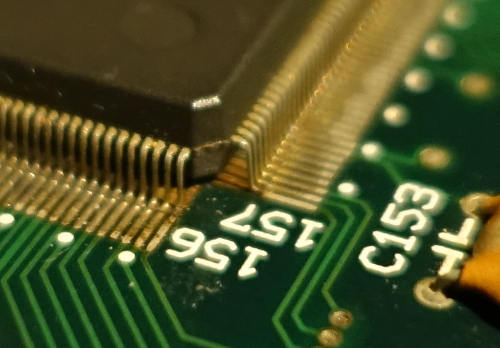
That's kind of hard to see on the photo, but it looks like the pad of the last pin (close to number 157) has way less solder than other pads - it doesn't look like it actually connects with the pin. I poked the pin very carefully... and sure enough, it moved very easily. I booted the board again and now simply touched the corner of the chip very lightly - the vertical bars easily disappear. At this point I'm convinced this is the culprit!
So I tried my best to solder it in place, but the pads being in sorry state made it a bit difficult (I wasn't able to clean it up much better than this), but eventually I managed for the solder to stick and the pin now didn't move:
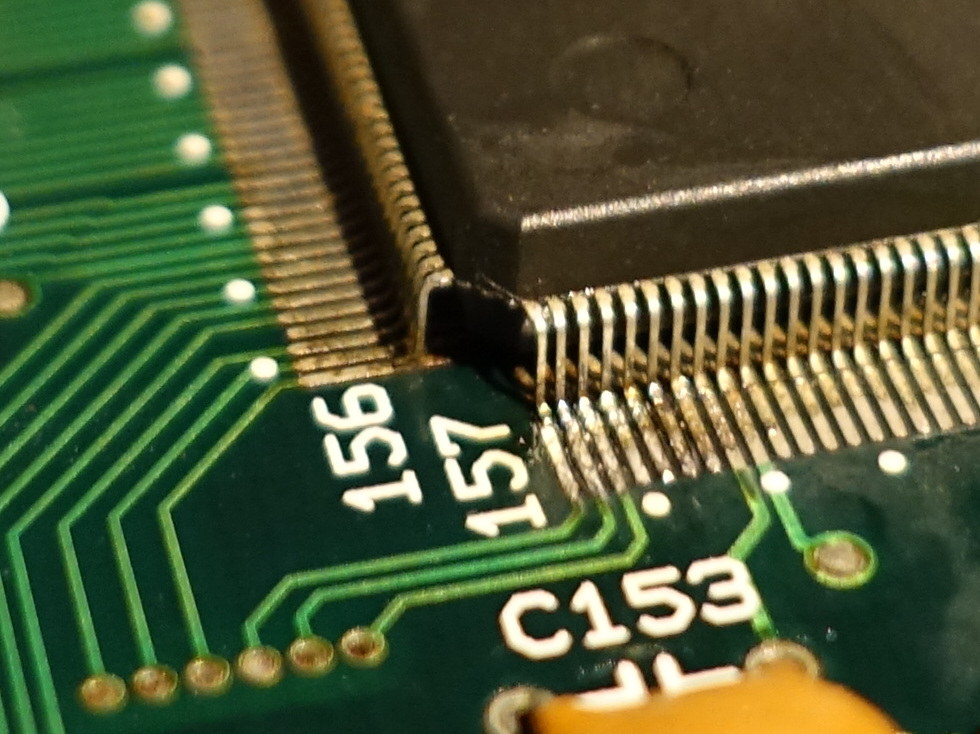
It still looks it's floating on this photo, but it's in fact firmly attached (I didn't manage to make it look better than this, the pads really don't take solder very well at this point), and multimeter test convinced me that the connection is now reliable enough. But does it work?
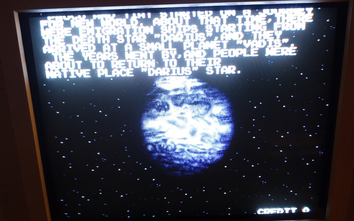
Yes it does! No vertical bars, no magic finger necessary. If this didn't work I was planning to connect enamel wire to the pin and solder it to the trace, but at this point I don't want to mess with these tiny pins anymore.
So suprisingly, it turned out that the problem was nowhere near the pins of the mask ROMs that I had to desolder - I either dislodged this pin while cleaning this area of the board, or it was already dislodged when I got it and it simply didn't visibly manifest when running Taito Cup Finals and Darius Gaiden just made the issue noticeable. Who knows Time to enjoy one of my favourite shmups of all time on the original hardware, and I couldn't achieve this without this guide so many thanks yet again!
with the intent of poking at all of the EPROM pins and seeing if I can see something off.
I found two suspicious things - pin 15 and 17 on 2 topmost graphics chips either didn't seem to display any activity, or only very occasionally the "pulse" diode lit up, while every other pin displayed some kind of logic state every time. I couldn't figure out what's the deal with pin 15, it doesn't seem like any traces go to it (so maybe it is supposed to be floating), but I actually did find what looked like broken connection from pin 17 to the via not far above it (at least I think that's how this connection is supposed to look like, hard to tell with socket in the way). I quickly soldered a jumper and booted up the board again, and....
... absolutely nothing changed, vertical bars were still there. And besides, the pin activity didn't change at all when I tried to push the board (which normally fixes the vertical bars), so maybe I should have expected it
So, back to the drawing board. For what felt like the millionth time, I looked closely at the board with magnifying glass, and this time what caught my attention was the graphics chip (TC0630FDP), the very corner closest to camera:
The pads behind the pins don't look the best - but in fact, it was way worse when I got this board, it was covered with brown gunk, especially in that area (you can still see it on the label) - so the first thing I did before even starting the conversion was thoroughly cleaning the board (had to use soapy water, isopropyl alcohol didn't cut it). I thought this area was worth examining since this is the graphics chip, and it's not too far from the spot on the board that seems most sensitive to pushing. Enhance:
That's kind of hard to see on the photo, but it looks like the pad of the last pin (close to number 157) has way less solder than other pads - it doesn't look like it actually connects with the pin. I poked the pin very carefully... and sure enough, it moved very easily. I booted the board again and now simply touched the corner of the chip very lightly - the vertical bars easily disappear. At this point I'm convinced this is the culprit!
So I tried my best to solder it in place, but the pads being in sorry state made it a bit difficult (I wasn't able to clean it up much better than this), but eventually I managed for the solder to stick and the pin now didn't move:
It still looks it's floating on this photo, but it's in fact firmly attached (I didn't manage to make it look better than this, the pads really don't take solder very well at this point), and multimeter test convinced me that the connection is now reliable enough. But does it work?
Yes it does! No vertical bars, no magic finger necessary. If this didn't work I was planning to connect enamel wire to the pin and solder it to the trace, but at this point I don't want to mess with these tiny pins anymore.
So suprisingly, it turned out that the problem was nowhere near the pins of the mask ROMs that I had to desolder - I either dislodged this pin while cleaning this area of the board, or it was already dislodged when I got it and it simply didn't visibly manifest when running Taito Cup Finals and Darius Gaiden just made the issue noticeable. Who knows
Time to enjoy one of my favourite shmups of all time on the original hardware, and I couldn't achieve this without this guide so many thanks yet again!
I have a Metal Black with a similar issue (ship and some layers don’t appear) and it definitely seems to be this custom being troublesome (pushing down fixes). Have had it reflowed multiple times but don’t want to keep stressing it. Will get a microscope and investigate further.