lukemorse1
Professional
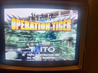
A story about a Tiger.
After taking quite a bit of time looking on the net for some information regarding Taito's Operation Tiger, I soon came up empty handed so I decided to make this post to hopefully help out others.
This is one of those boards you don't see a lot of, but on top of that, there is zero information as to the wiring of it anywhere...
(This may be a long shot but if anyone has a manual with the pinouts and they could upload it, that would be great!).
Because of this, I spent quite a bit of time trying to poke around and find the necessary points to get this board running however, it is far from complete.
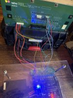
Here are some pictures of the filter board and the location of some pinouts to get this board to power up, display an image, and start a game.
Unfortunately I still haven't found the gun pot analog pinouts nor the speaker outputs yet as I was trying to get the game running first.
I wanted to try to illustrate the pins on the filter board but also where they would be located without the filter board (as some people may not have this piece).
I have tried my best to point out some of the power points as well as the Test, Coin in, Player 1 and 2 start buttons, and the select and back button for the test menu.
Although I have done my best here to find the various pins, There is a possibility something may not be 100% correct therefore I accept no responsibility if there are any mistakes with the pins.
*Please use this information at your own risk*
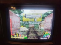
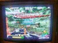
The pinouts were checked for operation on the filter board and I was able to get the game running but for my pcb, there is some graphic corruption (I believe caused by bad ram) so I still need to figure things out here.
Once again, because there was no information on the net, I wanted to put this out there to help out a little. Hopefully, if you have this board and you have been struggling to get it going, you can now at least get it to try to boot up.
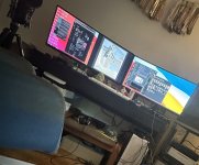
I realized this game is very picky about the monitor as well. I think it needs a 25khz? monitor or multi-sync monitor to display a stable picture. If not, the image will just roll and flash. If you run it through s-video, you will see white lines only that are scrunched up. It also didnt sync properly with a CGA to VGA converter either.
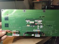
The pins marked on the first picture refer to the following:
The G1 connector top row (Pins 33-64 are all Ground/Earth)
This connector has pins 32 and 31 for +12v , Pins 30 and 29 for +13v (Used for the Audio Amp I believe), 28, 27, 26 are +5v
Pins 7 to 10 are all for video.
*REVISED VIDEO PINOUTS for this PCB*
On the "V" connector, the correct pins are Pin 1=Red, Pin 2= Green, Pin 3=Blue, Pin 4= Sync, Pins 5/6=Ground (GND).
If you dont have the filter board , The"G1" pinout for video is 7 = RED, 8= Green, 9=Blue, 10= Sync, . I originally had Red and Green backwards but when I switched them around again, the colors came back. The characters look human again and less zombie like. This revised pinout is correct. You will need to switch Green and Red only.
*Updated Pictures Below* The video pins on G1 correlate to the 7 pins on V. (They were connected to each other when I did a continuity check).
Connector S appears to be for the sub board related to the guns. (unsure of pinouts)
Connector C has the middle row of pins 33, 34, 35, 36 as +12V. (there were other points as well in the middle row but that should be enough. double check pin 36 as well) Pins 73 to 78 are all Ground.
Pin 57 is the "Select/Enter" button for the test menu and Pin 56 is the "Cancel/Back" button for the test menu *There is a possibility that these are also "shoot or bomb"? Im not 100% on it. Feel free to let me know below.
Pin 95 is Coin in (also connected to the G2 connector) and Pin 93 is Player 1 Start
Connector P is the power input area and it distributes power to the other pins mentioned above.
The nice part about this is there were test points (TP) above the connector which made it much easier to figure out what the power rails were.
The far left Pin 1 is +12v, Pin 2=+13v, Pin 3, 4, 5 = +5V, Pins 6, 7, 8, 9 = Ground
Connector G2 has odd numbered pins i.e. 1, 3, 7 , 9 etc on the bottom row and even number pins i.e. 2, 4, 6, 8, etc on the top row.
The pins I have found so far are:
Pins 50, 49, 48, 47 = GND , Pins 46, 45, 44 = +5V, Pins 43, 42 =+12v, Pin 39 = P2 Start, Pin 38 = Coin In, Pin 35 = Test ( * it is also Pin 91 on the "C" Connector which I forgot to label). Pin 34= P1 Start, Pin 30 = "Select/Enter/ maybe shoot"?, Pin 28 = "Back/Cancel/maybe bomb"?
The pins in between the other pins (not mentioned) read around 4.38v when I was probing them. I dont know which ones are the Analog inputs yet but Im guessing they are somewhere around there *If anyone finds out, please post below*
Double check the picture and the information here to double check it is correct and then try your board out and see if it boots up.
A bit of a write up here but just trying to contribute some info here that will hopefully prove useful to someone out there lol.
After taking quite a bit of time looking on the net for some information regarding Taito's Operation Tiger, I soon came up empty handed so I decided to make this post to hopefully help out others.
This is one of those boards you don't see a lot of, but on top of that, there is zero information as to the wiring of it anywhere...
(This may be a long shot but if anyone has a manual with the pinouts and they could upload it, that would be great!).
Because of this, I spent quite a bit of time trying to poke around and find the necessary points to get this board running however, it is far from complete.
Here are some pictures of the filter board and the location of some pinouts to get this board to power up, display an image, and start a game.
Unfortunately I still haven't found the gun pot analog pinouts nor the speaker outputs yet as I was trying to get the game running first.
I wanted to try to illustrate the pins on the filter board but also where they would be located without the filter board (as some people may not have this piece).
I have tried my best to point out some of the power points as well as the Test, Coin in, Player 1 and 2 start buttons, and the select and back button for the test menu.
Although I have done my best here to find the various pins, There is a possibility something may not be 100% correct therefore I accept no responsibility if there are any mistakes with the pins.
*Please use this information at your own risk*
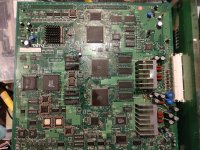
The pinouts were checked for operation on the filter board and I was able to get the game running but for my pcb, there is some graphic corruption (I believe caused by bad ram) so I still need to figure things out here.
Once again, because there was no information on the net, I wanted to put this out there to help out a little. Hopefully, if you have this board and you have been struggling to get it going, you can now at least get it to try to boot up.
I realized this game is very picky about the monitor as well. I think it needs a 25khz? monitor or multi-sync monitor to display a stable picture. If not, the image will just roll and flash. If you run it through s-video, you will see white lines only that are scrunched up. It also didnt sync properly with a CGA to VGA converter either.
The pins marked on the first picture refer to the following:
The G1 connector top row (Pins 33-64 are all Ground/Earth)
This connector has pins 32 and 31 for +12v , Pins 30 and 29 for +13v (Used for the Audio Amp I believe), 28, 27, 26 are +5v
Pins 7 to 10 are all for video.
*REVISED VIDEO PINOUTS for this PCB*
On the "V" connector, the correct pins are Pin 1=Red, Pin 2= Green, Pin 3=Blue, Pin 4= Sync, Pins 5/6=Ground (GND).
If you dont have the filter board , The"G1" pinout for video is 7 = RED, 8= Green, 9=Blue, 10= Sync, . I originally had Red and Green backwards but when I switched them around again, the colors came back. The characters look human again and less zombie like. This revised pinout is correct. You will need to switch Green and Red only.
*Updated Pictures Below* The video pins on G1 correlate to the 7 pins on V. (They were connected to each other when I did a continuity check).
Connector S appears to be for the sub board related to the guns. (unsure of pinouts)
Connector C has the middle row of pins 33, 34, 35, 36 as +12V. (there were other points as well in the middle row but that should be enough. double check pin 36 as well) Pins 73 to 78 are all Ground.
Pin 57 is the "Select/Enter" button for the test menu and Pin 56 is the "Cancel/Back" button for the test menu *There is a possibility that these are also "shoot or bomb"? Im not 100% on it. Feel free to let me know below.
Pin 95 is Coin in (also connected to the G2 connector) and Pin 93 is Player 1 Start
Connector P is the power input area and it distributes power to the other pins mentioned above.
The nice part about this is there were test points (TP) above the connector which made it much easier to figure out what the power rails were.
The far left Pin 1 is +12v, Pin 2=+13v, Pin 3, 4, 5 = +5V, Pins 6, 7, 8, 9 = Ground
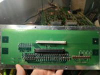
Connector G2 has odd numbered pins i.e. 1, 3, 7 , 9 etc on the bottom row and even number pins i.e. 2, 4, 6, 8, etc on the top row.
The pins I have found so far are:
Pins 50, 49, 48, 47 = GND , Pins 46, 45, 44 = +5V, Pins 43, 42 =+12v, Pin 39 = P2 Start, Pin 38 = Coin In, Pin 35 = Test ( * it is also Pin 91 on the "C" Connector which I forgot to label). Pin 34= P1 Start, Pin 30 = "Select/Enter/ maybe shoot"?, Pin 28 = "Back/Cancel/maybe bomb"?
The pins in between the other pins (not mentioned) read around 4.38v when I was probing them. I dont know which ones are the Analog inputs yet but Im guessing they are somewhere around there *If anyone finds out, please post below*
Double check the picture and the information here to double check it is correct and then try your board out and see if it boots up.
A bit of a write up here but just trying to contribute some info here that will hopefully prove useful to someone out there lol.
Attachments
-
 taito operation tiger pinouts.jpg185.9 KB · Views: 154
 -
 IMG20230126152049.jpg183.1 KB · Views: 166
 -
 IMG20230126154400.jpg380.5 KB · Views: 158
 -
 IMG20230126154414.jpg362.3 KB · Views: 147
 -
 IMG20230125130107.jpg161.8 KB · Views: 150
 -
 IMG20230125140523.jpg265.9 KB · Views: 140
 -
 IMG20230125140008.jpg98.2 KB · Views: 136
 -
 IMG20230125140332.jpg268.8 KB · Views: 172
Last edited: