Big_P Big_p
Grand Master
I am coming up on my 25th build of the TD-IO and have leant quite a few things about it. I thought I would share some of these to assist anyone else wanting to take on their own build.
They are definitely an intermediate to advanced build, that requires quite a good set up and a good level of SMD soldering skill. They are however not too hard if you have hot air, take you time and know what to look out for. I also typically have built boards for sale, so if soldering is not your thing DM me.
1. WHERE TO START?
I typically start at the power/buck converter as its probably the hardest thing to get right and is much easier to fix without lots of other stuff on the board.
The SIC437A is a tiny QFN package thats is seriously accurate and able to deliver a constant voltage up to 7A. To solder this hot air is a must (maybe a hot plate would work too). It has 5 pads underneath one of which is tiny and all of which are only 0.5mm apart.
To solder this i typically tin the pcb pads with a good quality lead solder. To check i am happy with it, I look at the board side on and make sure all of my pads have a very slight dome shape. They shouldn't be any higher than 0.5mm, but they should also look fully covered and smooth.
The bottom right and right side pads can be difficult to get to look smooth because they sink a lot of heat. Because of this the are also prone to overheating and solder mask damage. I have only done this once and in most cases if you caught it, its not terminal. It just looks a bit ugly. To avoid this if I am having trouble ill clean up the tinned pads with iso add a good flux and dome them with hot air. Over tinning these pads can lead to bridging under the SIC, under tinning can result in poor connection and/or ground issues. Make sure that all of the small pads on the top and left are domed well as its easy to only worry about the big ones. These are easier to fix later but its better/easier if they are well tinned now.
To solder, clean up the tinned pads with iso and apply plenty of a good flux. Sit the SIC437A on top of the pads and align it as best you can. If it slides off or slides to angle diagonally without flux but stays in place once you have added it, the tinning is probably about right. When in place, hit it with hot air and when the solder has melted, tap it gently with your tweezers to make sure all of the pads are aligned.
At this point I let it cool slightly clean up with iso and reflux. Then I put a little downward pressure with my tweezers and reheat to get it flat to the PCB and make sure the side pads are connected.
If you were ovely generous with the solder this can bridge pads on the side but you can clean that up later with your iron. Typically its the bottom pads that bridge first, then the left and right and finally the top. If all sides and/or all pads are bridged, you probably bridged underneath too, but if its just the bottom no issues, and the bottom and a few on the left is typically no issue either.
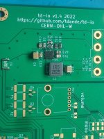
If you need to unbridge pads do so now with your iron and flux. Beware that cleaning up the right side or bottom now, can be when solder mask damage happens. As long as the top right pad is not joined to the other pads on the right, your good. The rest all go to ground. Its similar with the bottom 4 pads. As long as the 2 sets are not joined to each other, the pairs join under the IC anyway. Check the SIC437A is sitting flat and ALL the pads are connected, especially check the top and left as these are much easier to get right now before any of the other components go in. When you are happy start adding the other components around the buck converter. One thing to note here is that the top left resistors (one of them is 1k) control your output voltage (thats a bit of a crude description of how it works but its good enough). The point being use a 1% as a 5% can give you too much or too little voltage and an 0.1% typically leaves it at right on 3.3v (~3.302v) which can be too tight for some setups. Once all the other components are in but before you put the plastic Naomi type power connector on, plug the TD-IO into a JAMMA harness and check all of your voltages. Once you are happy with the voltages move on to 2. Should look like the picture but the top of the board is actually to the right in the picture.
TIPS, TRICKS & TROUBLESHOOTING
If you are not getting 3.3v typically one of your pads is not connected on the SIC437A.
If you are getting only a tiny voltage but a moderate to high ohms reading out of the 3.3v line its probably the top left one.
If you are getting a voltage reading way over 3.3v something is up around that 1k resistor.
I dont really know what bridged pads would do, because typically its obvious before this point and you fix them, but I assume similar issues.
You can see a few oversoldered pads in the picture (C11 & R3), if your having issue check anything that looks like that as the can hide a bad or non-existent connection. I typically clean them up just to make sure.
Only buy your SIC437A from a reputable supplier, use an Aliexpress one and you will be in a world of pain.
Also make sure the inductor is a good quality one, Bourns is spec'ed and thats what I use.
If you want to power a netdimm setup off the TD-IO try to get your 3.3v to read as close to 3.325v as possible. Even then it can be flakey with some setups being no problems and others refusing to be powered. If all your connections are good you should be close.
They are definitely an intermediate to advanced build, that requires quite a good set up and a good level of SMD soldering skill. They are however not too hard if you have hot air, take you time and know what to look out for. I also typically have built boards for sale, so if soldering is not your thing DM me.
1. WHERE TO START?
I typically start at the power/buck converter as its probably the hardest thing to get right and is much easier to fix without lots of other stuff on the board.
The SIC437A is a tiny QFN package thats is seriously accurate and able to deliver a constant voltage up to 7A. To solder this hot air is a must (maybe a hot plate would work too). It has 5 pads underneath one of which is tiny and all of which are only 0.5mm apart.
To solder this i typically tin the pcb pads with a good quality lead solder. To check i am happy with it, I look at the board side on and make sure all of my pads have a very slight dome shape. They shouldn't be any higher than 0.5mm, but they should also look fully covered and smooth.
The bottom right and right side pads can be difficult to get to look smooth because they sink a lot of heat. Because of this the are also prone to overheating and solder mask damage. I have only done this once and in most cases if you caught it, its not terminal. It just looks a bit ugly. To avoid this if I am having trouble ill clean up the tinned pads with iso add a good flux and dome them with hot air. Over tinning these pads can lead to bridging under the SIC, under tinning can result in poor connection and/or ground issues. Make sure that all of the small pads on the top and left are domed well as its easy to only worry about the big ones. These are easier to fix later but its better/easier if they are well tinned now.
To solder, clean up the tinned pads with iso and apply plenty of a good flux. Sit the SIC437A on top of the pads and align it as best you can. If it slides off or slides to angle diagonally without flux but stays in place once you have added it, the tinning is probably about right. When in place, hit it with hot air and when the solder has melted, tap it gently with your tweezers to make sure all of the pads are aligned.
At this point I let it cool slightly clean up with iso and reflux. Then I put a little downward pressure with my tweezers and reheat to get it flat to the PCB and make sure the side pads are connected.
If you were ovely generous with the solder this can bridge pads on the side but you can clean that up later with your iron. Typically its the bottom pads that bridge first, then the left and right and finally the top. If all sides and/or all pads are bridged, you probably bridged underneath too, but if its just the bottom no issues, and the bottom and a few on the left is typically no issue either.
If you need to unbridge pads do so now with your iron and flux. Beware that cleaning up the right side or bottom now, can be when solder mask damage happens. As long as the top right pad is not joined to the other pads on the right, your good. The rest all go to ground. Its similar with the bottom 4 pads. As long as the 2 sets are not joined to each other, the pairs join under the IC anyway. Check the SIC437A is sitting flat and ALL the pads are connected, especially check the top and left as these are much easier to get right now before any of the other components go in. When you are happy start adding the other components around the buck converter. One thing to note here is that the top left resistors (one of them is 1k) control your output voltage (thats a bit of a crude description of how it works but its good enough). The point being use a 1% as a 5% can give you too much or too little voltage and an 0.1% typically leaves it at right on 3.3v (~3.302v) which can be too tight for some setups. Once all the other components are in but before you put the plastic Naomi type power connector on, plug the TD-IO into a JAMMA harness and check all of your voltages. Once you are happy with the voltages move on to 2. Should look like the picture but the top of the board is actually to the right in the picture.
TIPS, TRICKS & TROUBLESHOOTING
If you are not getting 3.3v typically one of your pads is not connected on the SIC437A.
If you are getting only a tiny voltage but a moderate to high ohms reading out of the 3.3v line its probably the top left one.
If you are getting a voltage reading way over 3.3v something is up around that 1k resistor.
I dont really know what bridged pads would do, because typically its obvious before this point and you fix them, but I assume similar issues.
You can see a few oversoldered pads in the picture (C11 & R3), if your having issue check anything that looks like that as the can hide a bad or non-existent connection. I typically clean them up just to make sure.
Only buy your SIC437A from a reputable supplier, use an Aliexpress one and you will be in a world of pain.
Also make sure the inductor is a good quality one, Bourns is spec'ed and thats what I use.
If you want to power a netdimm setup off the TD-IO try to get your 3.3v to read as close to 3.325v as possible. Even then it can be flakey with some setups being no problems and others refusing to be powered. If all your connections are good you should be close.