What's new

buffi

Champion
Joined
Aug 12, 2019
Messages
1,134
Reaction score
2,536
Location
Sweden
Do you also have a stack of old Cave CV-1000 PCBs, and worry about the internal memory of the undumped CPLD at U13 going bad leaving you with an unusable board? Maybe you have a PCB which is already broken due to this?

The CPLD is programmed with device protection enabled, making it hard to dump its content. Luckily it's just a 44 pin device with not too many buses connected to it, so I went ahead and analyzed its behavior and programmed a compatible bitstream that allows you to burn any EPM7032AE CPLD and use that if the original one goes bad. This should allow you to repair a CV-1000 board where U13 has stopped working!

Information about exactly what the CPLD does, and how to make a compatible one for repair is available in this repo: https://github.com/buffis/cv1k_research/tree/main/U13_Research

The docs should be pretty thorough but let me know if you have questions.


NOTE: !!! THIS IS ONLY MEANT FOR REPAIRS FOR DUMB COLLECTORS LIKE ME.
PLEASE KEEP MULTI TALK AND THAT KIND OF STUFF OUT OF HERE !!!


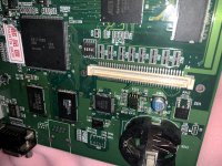
Some pics:
probes.jpg


soldered.jpg


chips.jpg


Bonus pic: My cat inspecting my PCBs for failing chips
pcbs.jpg
 

Attachments

  • soldered.jpg
    soldered.jpg
    264.7 KB · Views: 161
Minor thing about the programming: I was researching ATF150x, which I think is a compatible device family, and they can be programmed with 12V on OE1 to re-enable JTAG. Have a look on the PCB if that is isolated from everything else or put onto a jumper.
 
The JTAG pins are disabled to be used for IO so unlikely that would work here. Quartus doesn't allow JTAG programming when that setting is used at least.

In terms of wiring, OE1(pin# 38 ) is wired only to pin# 44 on the CPLD (High when reading from EEPROM/RTC, otherwise low.)

If someone wants to try using JTAG intead I would for sure appreciate it :)
Now that I have an expensive programmer that can deal with the CPLD I don't have to! :D

I have notes for all pins at
https://github.com/buffis/cv1k_research/blob/main/U13_Research/u13_pins.txt
if you are curious :)
 
Last edited:
Way to go, and kudos for experimenting on expensive hardware :)

Looking at the verilog file on github, it's a little strange that they didn't fit this stuff into the fpga?!
 
Way to go, and kudos for experimenting on expensive hardware :)

Looking at the verilog file on github, it's a little strange that they didn't fit this stuff into the fpga?!
Thanks, and yeah the PCBs are expensive... which is why it is good to be able to repair them if things break :)

Regarding fitting it on FPGA... no idea why it's the way it is. Maybe routing related?

FWIW, U13 does not seem needed for the SH-3 to boot from the U4 flash, and upload the bitstream to the FPGA.
It's possible to desolder U13 completely, and just wire its pin 5 (SH-3 CS6) to the output blitter pin 12 (goes to FPGA), and the board will still load U4 and attempt to boot up and show graphics

Since the graphics can't be read due to U13 not being in place, just garbage will be shown though. I actually have a video of that here:
View: https://youtu.be/5mip0LhE7GQ
 
Last edited:
Minor thing about the programming: I was researching ATF150x, which I think is a compatible device family, and they can be programmed with 12V on OE1 to re-enable JTAG. Have a look on the PCB if that is isolated from everything else or put onto a jumper.
You are correct on both points:
EPM7032 = ATF1502
EPM7064 = ATF1504
EPM7128 = ATF1508

Documentation states you should put a ~2K resistor on between +12V and OE1.
The JTAG pins are disabled to be used for IO so unlikely that would work here. Quartus doesn't allow JTAG programming when that setting is used at least.

In terms of wiring, OE1(pin# 38 ) is wired only to pin# 44 on the CPLD (High when reading from EEPROM/RTC, otherwise low.)

If someone wants to try using JTAG intead I would for sure appreciate it :)
Now that I have an expensive programmer that can deal with the CPLD I don't have to! :D

I have notes for all pins at
https://github.com/buffis/cv1k_research/blob/main/U13_Research/u13_pins.txt
if you are curious :)
It's not a problem to program a blank chip in JTAG even if those are used as I/O pins in the design. I guess the last JTAG instruction "enables" the logic.
If the device is already programmed and JTAG pins are used as I/O pins you can override that by applying +12V though a ~2K resistor to OE1.

I'm including the possibility to mount the resistor and feed +12V to OE1 in my designs using those CPLDs now (S18 multi, Sega C2 protection chip repro, etc.).
 
Oh that's very good to know, and should make it much easier for people to make these for themselves! (no need to buy an expensive Elnec programmer :) )

I will update the programming section of the repo with this info (with the disclaimer that I've not verified it myself).
 
That's also good to know that there's a non-obsolete drop-in replacement :)
Then maybe you don't have to use an ancient Quartus version to compile for them...

I just went with the same ICs that's on the board since that seemed cleanest. They're obsolete but still stocked for cheap on digikey
https://www.digikey.com/en/products/detail/intel/EPM7032AETC44-10/703885
 
I got a trial license for ProChip designer to experiment with the ATF150x chips. What a pile of #@$%, especially compared to Quartus!
In the end I used Quartus to design my stuff, then used ProChip to compile it. Though I should probably try Pof2Jed, as my trial has expired and I am definitely not going to pay money for that!
 
Back
Top