

MarkMaster compatibility is already pretty good but since release we have had reports that certain games don't work correctly. When we get these reports we try our best to fix the issue. This sometimes takes longer than we'd like but it's not always easy getting hands on original Mark III game carts for testing. So far we have learned that the rom does not have a standard for how it is routed in the cart. Different games can have it routed differently.
The first game we deployed a fix for was Outrun. This was a simple fix involving a single trace that needed to be cut. Most all MarkMasters out there should already have this fix done.
Our next report was that the game Castle did not boot. So we bought a copy, investigated, and came up with a fix. This fix is more complicated requiring a cut trace, adding a 74ls32 chip, and running 3 jumper wires. All units sold going forward will have this fix already applied with updated cart pcbs coming soon. You can add this fix yourself if you wish. The materials needed cost less than $2.
Instructions will follow below.
What needs to be done:
1) Power the LS32: tap ground and Vcc wherever is convenient for you (I chose the GAL)
2) Cut a trace on the Mark III connector (4th pin from the left at the front)
3) Chose one of the gates on the LS32
4) Connect pin 14 of the GAL to one of the inputs of the gate
5) Connect the other input of the gate somewhere below the trace cut.
6) Connect the output of the gate somewhere above the trace cut or direct to the pin of the connector.
Below is the procedure I chose to do the mod. I believe this is the cleanest way to do it and still fit nicely into the cart shell.
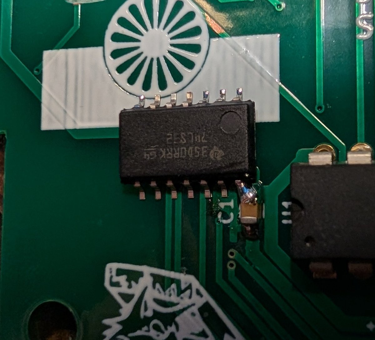
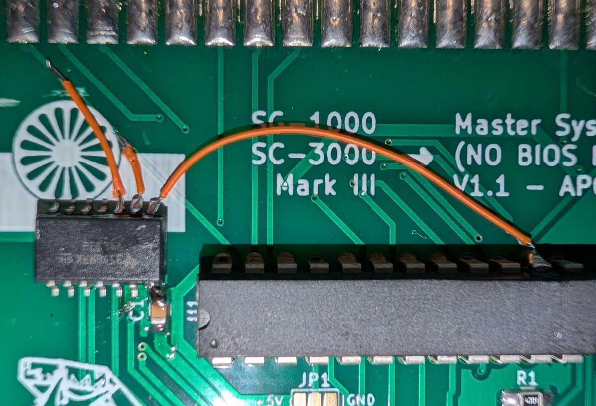
Step 1: Using the cap at C1, solder pin 14 of the LS32 to the topside of the cap. This will provide 5v for the chip. Notice the orientation of the chip is upside down allowing pin 14 to be soldered.
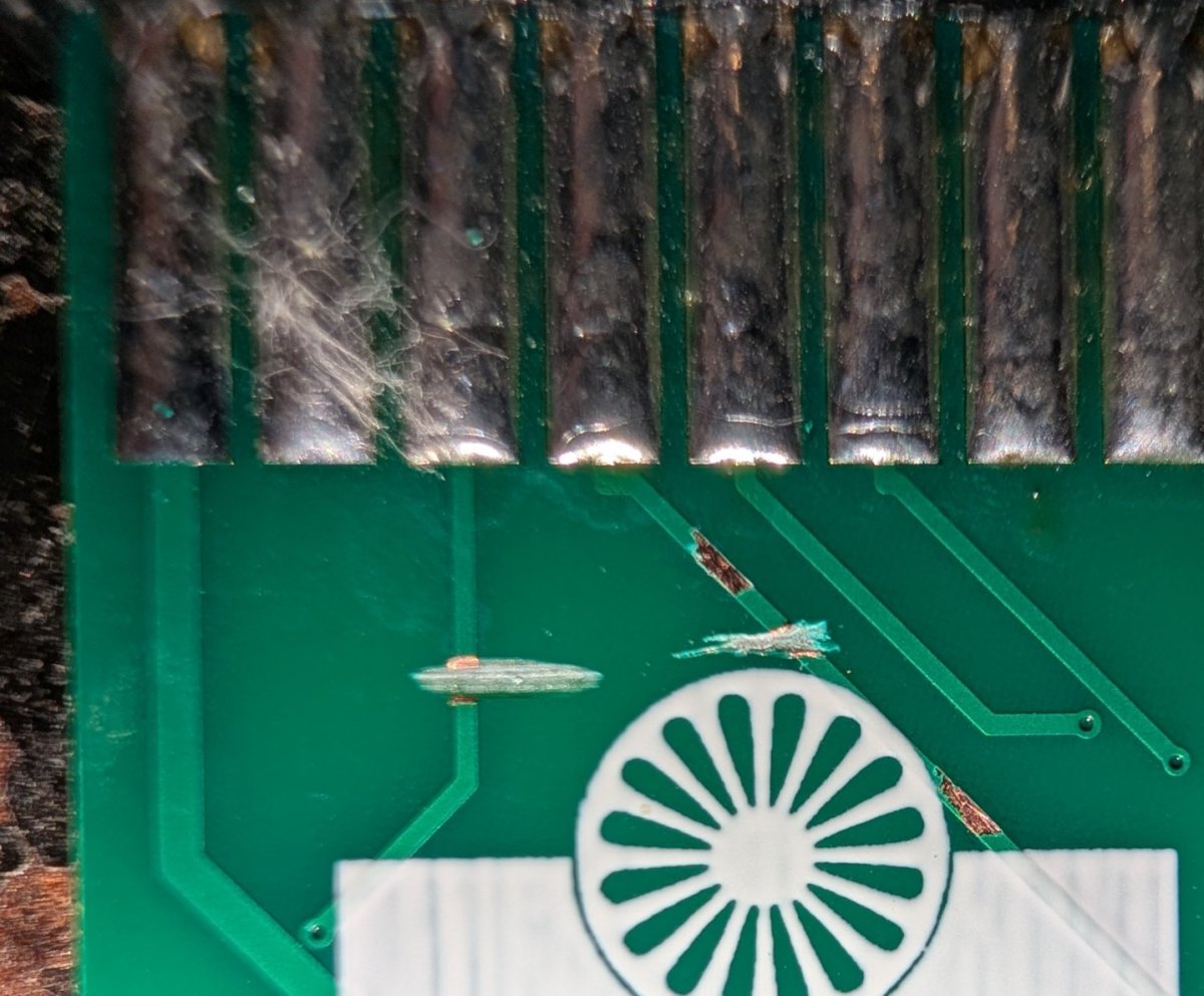
Step 2: Cut the trace connected to pin 4 from the left of the cart connector. Leave enough space so you can scratch and expose a copper patch above and below the cut. We will solder to these two areas soon. (Notice the cut trace on pin 3 was the fix for Outrun and not part of this fix)
Step 3: Connect pin 14 of the gal chip to one input of the LS32. I used pin 1 of the LS32.
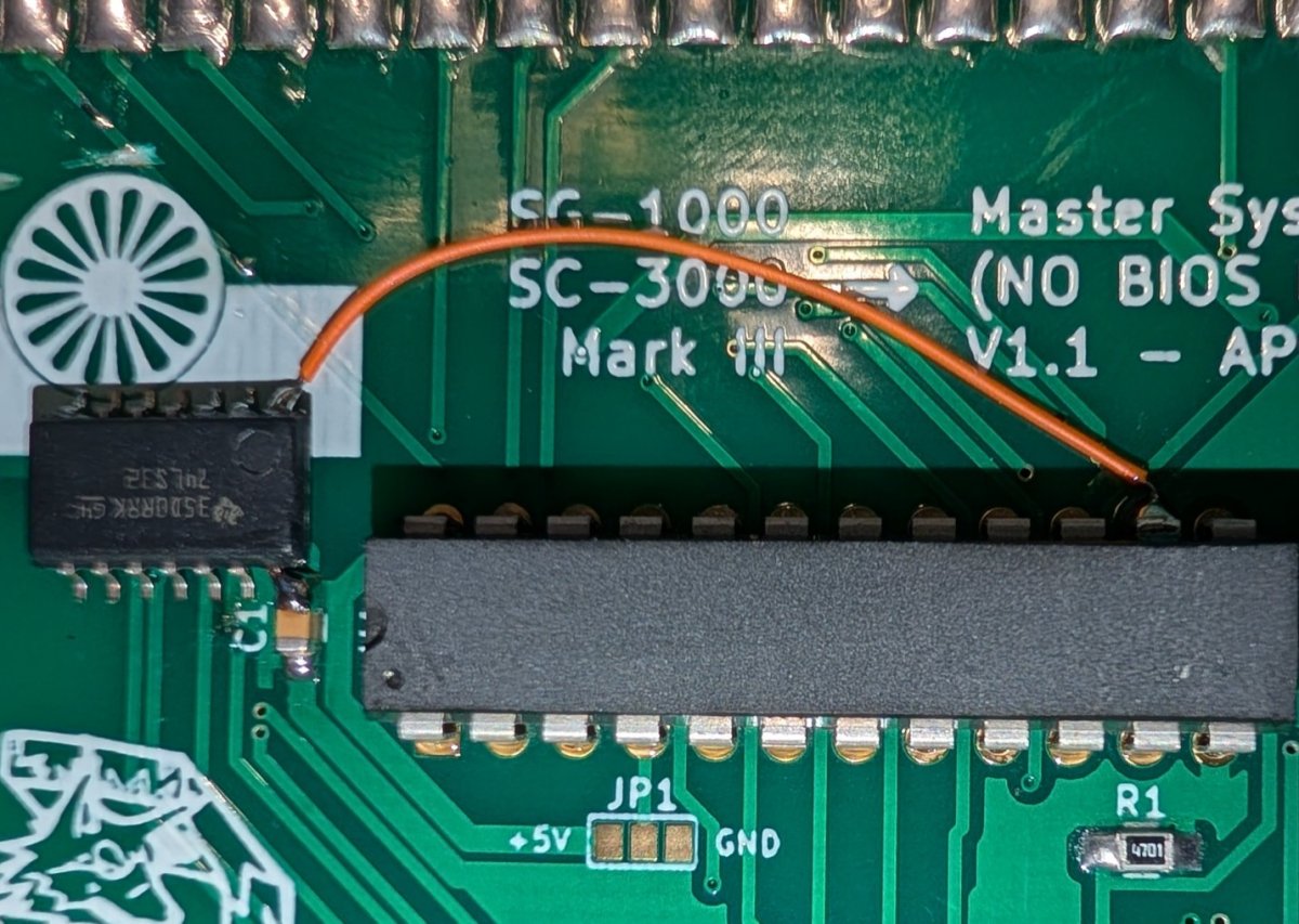
Step 4: Connect the other input of the same gate to the scratched trace BELOW the trace cut.
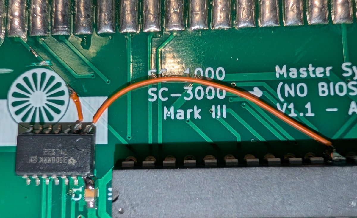
Step 5: Connect the OUTPUT of the gate to the scratched trace ABOVE the trace cut.
Step 6: Finally, connect ground to the LS32 chip on pin 7. I tap ground from the bottom of the C1 cap.
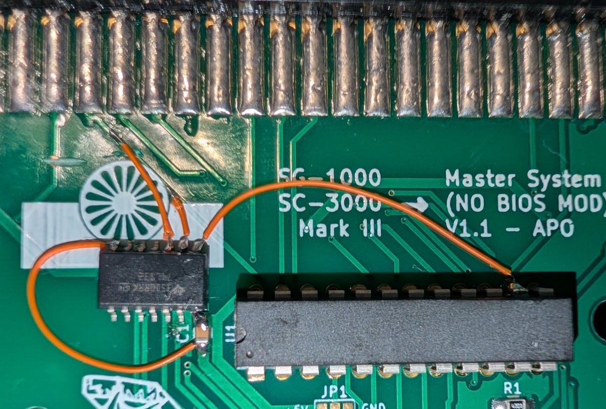
You can use a little hot glue or similar the further secure the LS32 chip down. If you prefer to use a larger DIP version chip you can do so. Pinout is the same.
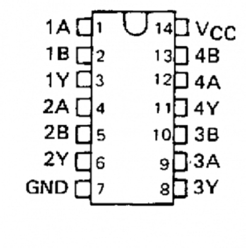
For reference here is the pinout of the LS32 chip. A and B represent inputs and Y represents outputs. You can use any gate but must use the same gate for all three connections.
The first game we deployed a fix for was Outrun. This was a simple fix involving a single trace that needed to be cut. Most all MarkMasters out there should already have this fix done.
Our next report was that the game Castle did not boot. So we bought a copy, investigated, and came up with a fix. This fix is more complicated requiring a cut trace, adding a 74ls32 chip, and running 3 jumper wires. All units sold going forward will have this fix already applied with updated cart pcbs coming soon. You can add this fix yourself if you wish. The materials needed cost less than $2.
Instructions will follow below.
What needs to be done:
1) Power the LS32: tap ground and Vcc wherever is convenient for you (I chose the GAL)
2) Cut a trace on the Mark III connector (4th pin from the left at the front)
3) Chose one of the gates on the LS32
4) Connect pin 14 of the GAL to one of the inputs of the gate
5) Connect the other input of the gate somewhere below the trace cut.
6) Connect the output of the gate somewhere above the trace cut or direct to the pin of the connector.
Below is the procedure I chose to do the mod. I believe this is the cleanest way to do it and still fit nicely into the cart shell.
Step 1: Using the cap at C1, solder pin 14 of the LS32 to the topside of the cap. This will provide 5v for the chip. Notice the orientation of the chip is upside down allowing pin 14 to be soldered.
Step 2: Cut the trace connected to pin 4 from the left of the cart connector. Leave enough space so you can scratch and expose a copper patch above and below the cut. We will solder to these two areas soon. (Notice the cut trace on pin 3 was the fix for Outrun and not part of this fix)
Step 3: Connect pin 14 of the gal chip to one input of the LS32. I used pin 1 of the LS32.
Step 4: Connect the other input of the same gate to the scratched trace BELOW the trace cut.
Step 5: Connect the OUTPUT of the gate to the scratched trace ABOVE the trace cut.
Step 6: Finally, connect ground to the LS32 chip on pin 7. I tap ground from the bottom of the C1 cap.
You can use a little hot glue or similar the further secure the LS32 chip down. If you prefer to use a larger DIP version chip you can do so. Pinout is the same.
For reference here is the pinout of the LS32 chip. A and B represent inputs and Y represents outputs. You can use any gate but must use the same gate for all three connections.
Last edited: