What's new
@Softdrink yea not bad, I wanted to utilize the threaded posts/mounting point just behind the sound amp PCB, so really it would just be adding that to this design more or less.
 
Glad to see you're still at it Franco, looking awesome, especially the new insides of the CP's, great work as always! :D

Thanks buddy! :) They're gonna get a hella lot cleaner yet, just you wait ;)

Be keeping an eye out for this, that looks awesome. I'm over free handing inserts and ending up with flogged out holes from excessive adjustment.

I was hoping to get this finalised by now and uploaded. I made some tweeks to my V1 version and I thought I was making a complete insert press for someone else and was going to 'prove out' my mods on that one but I'm not sure if they still want it making. I've made a BOM for it and I've done the mods to the part files/STLs. If you wanted to try them out I can hook you up with them before I release them publicly. If so just shoot me a PM.

You always do such clean, fantastic work, Franco. 👍 I would be lying if I said I didn’t learn clean cabling and mod work from you. 😉

Cheers bud, most kind words! I took inspiration for doing tidy wiring from a thread over at BYOAC many many moons ago and I've tried to work hard on in since. I'm really happy if you've picked something up from me too :thumbup: I've been messing with some CP wiring which I'll post in a later update. My wiring OCD may have gone too far but I'll let you be the judge of that :D
 
Apologies for the delay in updates. Any free time I've had has been (trying) to work on things but I thought I should try and get something uploaded at least before I forget what I've done. I'll not stick everything in this post as it will take too long.

The next thing I worked on wasn't really planned but it's something that came about as I was working on things. I've got both cabs running off an Airlink UK-JA0750 and I had the power leads running as so:

i-DD7krtd-XL.jpg


The problem with this is that every time I pulled the cabs out to work on the power cables would pull forward. When I went to push the cabs back the wires would get caught under the wheels and it was a ball ache fiddling with them the whole time. I thought about mounting the stepdown on the wall between the cabs but I didn't really fancy doing that. Another issue I found during working on the cabs is that I couldn't fit the smallest PC I have inside the Vewlixs. This meant I would have to get a smaller PC or run it external and have more wires running behind the cabs which I really didn't fancy. So, rather than using less wires, I bought a crap load more :D

i-nmGW8fV-L.jpg


And ended up doing this:

i-TMV8C3K-L.jpg


I added a 3m secton of 100x50mm Univolt trunking and bought various gang accessory boxes and plugs & media modules. The idea being that I could use the trunking as essentially a power strip with some mutimedia IO functionality. My desk and gaming rig is on the other side of the room so I figured I could also put the second PC under my desk and run all of the cabling through the trunking. That would save having PCs in or next to the cabinets.

The cab nearest the wall has a NEMA 5-15P US power socket (that JP JIS C 8303 plugs fit just fine), two USB ports that are connected to 10m USB repeater cables, a HDMI socket with a 10m cable attached and a Cat6 RJ45 socket. I had to learn to wire RJ45 sockets with was fun and I added a ~10m cable to this too.

i-h64Gn7H-L.jpg


The other cab has the same setup but I also added a AC voltmeter to display the AC output from the stepdown. I can't do anything to adjust the output but it's nice to keep an eye on what's being output. So far I've noticed it range from 103-107V.

i-NsTczLn-L.jpg


Next to the cabs I've got a B&O MX4200 setup for consoles/MiSTer so I've added a UK plug to this with a power switch and another Cat 6 RJ45.

i-xD5SsQc-L.jpg


Couple of pics during wiring:

i-85WcV5Z-L.jpg


i-ZvwGmBH-L.jpg


i-ShqpXzF-L.jpg


Couple bonus pics of trimming the ends of the trunking facia with the use of a printed template:

i-KVt8hGn-L.jpg


i-fRwdF3S-L.jpg


Cable management/routing/handing during all of this was 'fun'. I added a partition to the trunking to keep the 100v and 230v wires away from the data cables which are in the top section. I added labels to the cables so I knew what I needed to plug in where when I got to the PCs at the other end. I'll try and get a picture/video of where the wiring goes to later.

The trunking cover fits on pretty tightly and isn't designed to be put on/off and I was quite concerned about things not working after fitting the trunking so I was really diligent on testing all of the USB, HDMI and ethernet connections all the way through wiring so I could be confident everything would work when I fitted the fascia. Now, I tested all of this using a laptop and everything worked fine and so I finished off the routing under my desks and fitted the covers. When I plugged everything into my main gaming rig I found one of the Brook UFBs wouldn't be recognised properly :cursing: I had to do a load of troubleshooting at both ends of the cables to find out what I feared the most and that one of the USB repeaters was now not working properly :cursing: I ordered a different type of USB repeater extension cable from Amazon and painstakingly replaced that one cable from the whole cable run which was a massive pain. This then worked fine but then one of the other extensions started playing up :mad: I then had to do exactly the same thing again! Touch wood though, after changing the repeaters to another brand (Amazon basics, believe it or not) they've worked just fine.

This is how the wiring then looks when hooked up to PC:

i-PtVkqmk-L.jpg


I've aligned the sockets to be in the centre of the cabs so that even when I pull them far out the cables then trail between the wheels when pushed back.

As the power/IO bar is low I've used 90 degree cables and/or connectors to allow the cabs to be pushed up close to the wall. Not pictured (I'll add later) is a strip/bar I've screwed to the floor to a) stop the cabs being pushed back too far and b) align them perfectly.


That's it for this part of the update. I've got loads more of (hopefully more interesting :unsure: ) stuff to add....hopefully soon!
 
Lovely stuff. I was actually considering doing something similar behind my cabs (though for my case it's less about power and more about managing AV connections for streaming).
 
Soooo, I've been really slack at working on the cabs with limited time and I've been even slacker posting updates. I have got some work done though so I thought I'll try and get caught up as it might spur me on to put some time aside do a bit more....

Not entirely sure where to start and I've probably forgotten loads of stuff but here goes....

Fan upgrade

The stock fans in my cabs, like most Vewlix's I'm sure, were loud as fuck.

This was the state of the fans when I first got the cab:

i-H8W5kJ2-L.jpg


Luvverly <X

Even after cleaning them they still sounded like a harrier jump jet winding up.

There are two 120mm fans in the Dia blues, one at the bottom of the cab and one behind the monitor. I looked at a few options for replacements and balked at some of the prices for fans, especially when I needed to buy four. I thought I would start with something cheaper and see how they go. In the end I picked up a [five pack of Arctic F12 fans] from Amazon for ~£21.

i-CZzzVFx-L.jpg


The original fans had been hardwired in with some closed end crimps so I had to cut the fans off.

i-nWrq94c-XL.jpg


The OG fans are bolted all the way through and so have those white nylon tubes to stop the flanges from bending :whoopsie: I wanted to bolt the replacement fans in the same way and so I printed some supports for the flange centers:

i-jxdjVZc-XL.jpg


The fans came with a three pin non-polarised connector. I've got some pin headers that I could attach to the stock wiring but I wanted to use something polarised so that I don't run the risk of plugging things in back to front, especially when rummaging around in the back of the cab. Using a connector means I can always easily swap them out if required. I had ran out of 2 pin JST YL connectors so I used some spare JST XH connectors I had. They don't do a wire-wire connector so I soldered a header onto the fan and crimped a connector onto the cab side. I only needed 12v and GND so I tucked the sense wire into the outer heat shrink.

i-sH5S8r8-L.jpg


i-vjhcJgQ-L.jpg


All done:

i-bQqdf6x-L.jpg


Now wasn't that exciting :sleeping:

The noise from the fans is a massive improvement though. I've uploaded a video [here] where you can hear the difference between the stock and upgraded fans.

I'll continue with some more updates later....
 
So most things I had been working were not concurrent so the update order doesn't really matter. I'll update progress on the sub panel next.

Sub panel

As well as arcade hardware, I'm running various consoles in the cabs so I need some way of controlling certain console buttons that cannot be mapped to the CP controls. For a start I wasn't really sure exactly what buttons I would need, and to be honest I'm still not 100% set now. I started out by trying to design a panel that other people might also want to use but I think my use case will be different to other peoples and so I eventually decided to work on a panel to suit me. If people are interested I might look to make some generic panels further down the line.

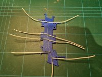
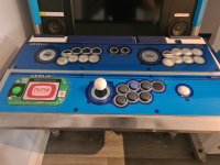
My initial panel design was fairly generic and not too dissimilar from others out there because at this point I didn't really know what I wanted:

i-NtBPXWS-L.png


There were three 30mm buttons per player (not knowing what they needed to control at this point). A hole on both sides for a power switch so I can power cycle the Brook UFBs when changing consoles, a hole for a volume control and for a headphone jack.

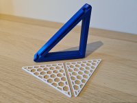
I printed a mocked up panel to play about with. I couldn't quite get the whole thing in one piece on the print bed so I split it in two and added rebates so it would assemble correctly once put together.

i-gBRX8Nw-L.jpg


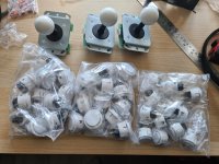
I populated the CP with some god awful 30mm snap ins I got cheap for use in a wiring jig many years ago. I added a B50K pot and some rocker power switches. Pro tip, don't forget to turn off your soldering iron at night :whistling:

i-xG667Vd-XL.jpg


My office smelt lovely in the morning after that 8| The panel was fucked but it could have been far worse X/

I printed another but without the power switches at this point and then worked on the audio side of things. My cabs are in the corner of my office and they are right next to my daughters bedroom, hence the reason for wanting headphone support. I also want to be able to mute the cab speakers and have amplified headphone audio when the headphone jack is inserted. I was initially going to use some Schiit Fulla DAC/amps as they would work a treat but they were just going to take up far too much route under the CP.

Instead I bought some headphone amplifiers off ebay as well as some DPDT 1/4" stereo jacks. I also had some 3.5mm audio jacks left over from years ago so I made some mounts for them and the amplifiers.
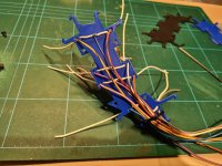
i-fQcJsdH-XL.jpg


Sexy test wiring ||

i-KHttZfN-XL.jpg


Neatened up a bit:

i-PvPtnzs-XL.jpg


With no headphones inserted the volume pot controls the line level audio before it goes to the Taito amp and cab speakers. With the headphones inserted, the audio is cut from the cab speakers. The (sub panel volume pot controlled) line level audio then goes to the headphone amp and then to the audio jack/headphones. It works really well, it's just a bit more 'wirey' than I would like. If I get some more time in the future (lol) it would be nice to consolidate more of it onto a PCB or two.

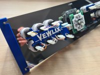
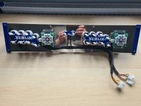
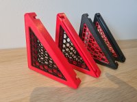
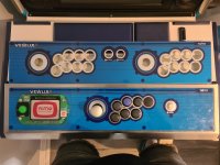
This is my latest (6 months ago) version of the sub panel:

i-fLNKs7h-XL.jpg


So, top left and top right are two sets of 12mm illuminated buttons, similar to [these].

One of them (for each player) is the latching type and used for switching the Brook UFBs on and off when changing systems as you need to hold different CP buttons whilst power cycling them to set the mode. Secondly, the PCs I'm running are external to the cabs and I have USB power set to always on. I don't want to keep the Brooks powered when not in use so this would allow me to switch them off also. The LED ring also indicates when they are on/off.

The other 12mm button for each player is for a momentary type for the Turbo key and LED from the Brook. It works fairly well, the only thing to improve it would be if you could adjust the auto fire frequency. Still a worthy addition though. Once again the LED ring would indicate if any button has turbo applied.

All the white buttons are 24mm, I don't feel the need to use 30mm. The two in the center would be for P1 'Share' (Select/Back) and the other would be P1 'Home'.

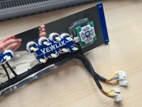
The single 24mm buttons on each side of the panel would then be the 'Touchpad' buttons. I'm not running PS4/5 myself but my original though would use these as credit buttons for MAME etc. Now I'm using the [Coin Reject Button Kits] that frees up a 'designated' credit button and so I may scrap or repurpose that.

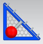
In the model above there are two rear mounted Neutrik USB ports in the middle of the panel. Ideally I would like these towards the outer edge but they would foul the mount I have my Brook UFBs on, so for my panel they would need to be somewhere around there. I might change tactic on these now and use more of a low key method similar to what I used to mount the USB extenstions/ports in my [MiSTer Ironclad case]

20230109_115856-XL.jpg


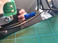
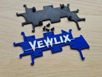
As i was using a tinted clear panel for the Ironclad I kept installation hardware down a minimum (i.e. none) as I wanted it to look as clean and unobstructed as possible. The Vewlix sub panels are opaque and the cables may be subject to more stress with the CP opening/closing so I've been experimenting with a different mounting method for that.

i-8BH63cz-L.jpg


That's it for the sub panel for now. I need to get some time back on the cabs and play some games ( :rolleyes: ) to double check what 'admin' buttons I need for each console.
 
Control Panels

Both of my Vewlix's came with 1L7B panels. I wanted to get a 2P panel for the hori cab and I thought I might as well replace the 1P panel in the tate cab to get rid of the card reader. After playing a few games I decided to go for 1L8B and 2L16B panels. Now, I'm not expecting to play a lot of games that need 8 buttons but some games I was playing just made sense to have four buttons on the bottom row. I contacted Alberto and ordered both panels in May 2022. The 2L16B was a stock item but he needs to make the 1L8B. The 2L16B landed in August 2022.

The quality of the panel is fantastic. Alberto warned me that the colour of the overlay wasn't 100% true to the original. In fact, it's very close when viewed directly above:

i-3bfz2TM-XL.jpg


However, when viewed at an angle the colour does change and appears darker, presumably due to the metallic in the overlay:

i-VXcQz7j-XL.jpg


Just to note, I'm not complaining here, Alberto warned me about this up front and I'm very happy with the panel. Since then Alberto has told me he's working on a new overlay for the Dia Blues and I'm going to get a matching 2L16B overlay to match the 1L8B when it's ready. :thumbup:

I have got the 2L16B panel wired up. I got a load of Seimitsu Sanwa OBSF-24/30 buttons and LS-56-01's from Aracde world:

i-XkNwXbH-XL.jpg


First, I made some CP stands to make it easier to work on populated CPs:

Parts_Blue-L.jpg


Main-L.jpg


NX_2-M.jpg


I also made some different coloured versions for some friends:

20220808_150419-L.jpg


I've always tried to do neat CP wiring and I thought I would try and improve things further over previous efforts. As part of this I printed some assemblies to fit around the buttons:

i-z4NjtDh-XL.jpg


The idea being that a lot of the wiring will be hidden inside the assembly/sandwich. To keep the amount of wires down I made a common ground 'spine' to connect to the buttons:

i-RhnD66B-L.jpg


The rest of the messy wiring is then fed through and sandwiched in the assembly:

i-JpwVkKG-XL.jpg


I printed some tie wrap bases to help with the cable management:

i-3rMVnpR-L.jpg


All done:

i-gP6Q6jd-XL.jpg


i-RDLvw6Z-XL.jpg


i-GcKxV5g-XL.jpg


Now that I know I'm getting a replacement CPO I'm going to need to rework some of this but I enjoy doing it so that's fine ^^
 

Attachments

  • i-GcKxV5g-XL.jpg
    i-GcKxV5g-XL.jpg
    136.9 KB · Views: 58
  • i-RDLvw6Z-XL.jpg
    i-RDLvw6Z-XL.jpg
    190.7 KB · Views: 40
  • i-gP6Q6jd-XL.jpg
    i-gP6Q6jd-XL.jpg
    154.1 KB · Views: 43
  • i-3rMVnpR-L.jpg
    i-3rMVnpR-L.jpg
    126.4 KB · Views: 42
  • i-JpwVkKG-XL.jpg
    i-JpwVkKG-XL.jpg
    257.3 KB · Views: 41
  • i-RhnD66B-L.jpg
    i-RhnD66B-L.jpg
    195.6 KB · Views: 40
  • 20220808_150419-L.jpg
    20220808_150419-L.jpg
    112.9 KB · Views: 38
  • NX_2-M.jpg
    NX_2-M.jpg
    42 KB · Views: 39
  • Parts_Blue-L.jpg
    Parts_Blue-L.jpg
    123.9 KB · Views: 43
  • i-XkNwXbH-XL.jpg
    i-XkNwXbH-XL.jpg
    206.8 KB · Views: 42
  • i-VXcQz7j-XL.jpg
    i-VXcQz7j-XL.jpg
    292.5 KB · Views: 41
  • i-3bfz2TM-XL.jpg
    i-3bfz2TM-XL.jpg
    187.1 KB · Views: 56
  • i-z4NjtDh-XL.jpg
    i-z4NjtDh-XL.jpg
    200.9 KB · Views: 40
  • i-z4NjtDh-XL.jpg
    i-z4NjtDh-XL.jpg
    200.9 KB · Views: 41
  • i-GcKxV5g-XL.jpg
    i-GcKxV5g-XL.jpg
    136.9 KB · Views: 42
  • i-RDLvw6Z-XL.jpg
    i-RDLvw6Z-XL.jpg
    190.7 KB · Views: 45
  • i-gP6Q6jd-XL.jpg
    i-gP6Q6jd-XL.jpg
    154.1 KB · Views: 40
  • i-3rMVnpR-L.jpg
    i-3rMVnpR-L.jpg
    126.4 KB · Views: 38
  • i-JpwVkKG-XL.jpg
    i-JpwVkKG-XL.jpg
    257.3 KB · Views: 34
  • i-RhnD66B-L.jpg
    i-RhnD66B-L.jpg
    195.6 KB · Views: 38
  • 20220808_150419-L.jpg
    20220808_150419-L.jpg
    112.9 KB · Views: 37
  • NX_2-M.jpg
    NX_2-M.jpg
    42 KB · Views: 45
  • Parts_Blue-L.jpg
    Parts_Blue-L.jpg
    123.9 KB · Views: 39
  • i-XkNwXbH-XL.jpg
    i-XkNwXbH-XL.jpg
    206.8 KB · Views: 38
  • i-VXcQz7j-XL.jpg
    i-VXcQz7j-XL.jpg
    292.5 KB · Views: 45
  • i-3bfz2TM-XL.jpg
    i-3bfz2TM-XL.jpg
    187.1 KB · Views: 49
Monitor woes.....

I've got two Vewlix Dia Blues with P32L050 monitors. A few months back one of them stopped displaying an image. Power etc to the monitor is fine and it's powering on and I know it's at least getting a signal as you can see the displayed input resolution via the OSD but no image is displayed. I tried both DVI and VGA inputs with different sources and the result is the same.

As I have two cabs with identical monitors I stripped them down and swapped PCBs to narrow down where the issue lies and this pointed me towards the Toshiba V28A00122300 PCB, this fella:

i-9CnP8hD-L.jpg


I was speaking with @Monstermug and he suggested shotgunning the [THC63LVDM83D ICs] as they sounded like they could be the culprit.

i-MZn3WmZ-L.jpg


I ordered some from ebay..... and this is how they arrived :cursing:

i-FHpNbnZ-L.jpg


I'm sure rattling around in a zip lock bag as they made their merry way to be will have done them no end of good X/ I mean, they may be fake but at least give them a chance!

Anyway, @Monstermug kindly changed them for me but sadly this made no difference. The chips could be fake, damaged or this just isn't the issue. There is a BGA on the board which it could be. Monstermug is going to have a go at reflowing the BGA in a last ditch attempt as rescuing the PCB and monitor. I've looked around and put up a wanted ad for a replacement V28A00122300 PCB but not too surprisingly I've not had much luck.

I always knew I would upgrade the monitors at some point but I thought it would be out of choice rather than necessity. Damn this modern flaky tech! I had been looking at various monitors anyway and stumbled across a great deal on a couple of refurbed LG 32GN550 monitors on ebay which I got for ~£190 each

i-zkK5F3t-L.jpg


i-DbMFMzp-XL.jpg


I want to keep the OG monitors but I'm going to make some mounts for these so I can fit them in the original bezels. So far I've modelled up the displays and started to work on the mount design....

20221009_073505-XL.jpg


LG_32GN550_CAD_BACK-XL.png


LG_32GN550_CAD_FRONT-XL.png


View: https://youtu.be/U7bFdMMfCm0


I went far too far detail wise compared to what geometry is actually needed for development but it was all good fun.

More on this to follow.....
 
Love what you're doing with these. I've just gotten my first Vewlix cabinets so I'm taking a lot of notes...


Those headphone kits are a fantastic idea! Any chance you have a parts-list for the less technologically inclined?
 
Curious to see what you come up with!

I'm curious to see if it will work :D


Love what you're doing with these. I've just gotten my first Vewlix cabinets so I'm taking a lot of notes...


Those headphone kits are a fantastic idea! Any chance you have a parts-list for the less technologically inclined?

Sure, no problemo.

I used:

[50k Dual Gang Linear Potentiometer]
[MAX4410 Mini Amp Headphone Amplifier]
[3.5mm Stereo Jack Socket] x2
DPDT 1/4" Stereo Jack Socket - Panel mount - 9 pins

The top three items are links.

A log pot would probably be more suitable for this but I was struggling to find some dual gang ones at a reasonable price.

The 3.5mm Stereo Jack Sockets are just some I had left over in my parts bin from previous projects. They're switched sockets but I'm not using that function at all, they're literally just so I can get a signal from a 3.5mm stereo cable. The rectangular shape of them meant they were ideal for fitting in the 3D printed housing though.

I've not put a link to the DPDT 1/4" Stereo Jack Socket as I actually struggled to find these in the UK. The ones I bought were two from a guy who was clearing out his dads electronics inventory. They seem to be a lot easier to get hold of in Europe, the US and Aus though. (EDIT: [Here's] a example for a source in the US)

Let me know if you need any more help or info. I can knock up a wiring diagram if that would help.

Disclaimer: I'm in no way an electrical engineer or expert in this type of thing. I just cobble stuff together and see if it works :whistling:
 
Thank you so much, the parts list is great to have. If making up a diagram was something you were going to do eventually I would appreciate it, but I don’t want to trouble you further if not.
 
Hi @FrancoB - I just want to say thank you for documenting your restoration and mods in this thread. I bought a Dia Blue from Mo this year too and you've been somewhat of an inspiration. :)

I've just ordered a 2L16B control panel from alberto and I am very much looking forward to having friends over to play on it instead of awkwardly using controllers for 2P or taking it in turns like we have to currently!
 
@ConvincingJohn - Apologies for the late reply. I wanted to get back to you with a diagram but some other things got in the way. I am picking this up again now and working on the sub panels. I need to make some more looms up for them so I'll put together a diagram at the same time.

@bubble bobble - Ah great stuff, glad to hear you got one off Mo, he's a good guy! You'll have to get some pictures up! You'll love @alberto1225 's panel, he does fantastic work. :thumbsup:

I've got a few things to update which I'll do when I get time. Apologies for not replying in general sooner, I like to reply alongside updates so I'm not 'spamming' the thread too much but because I've not been posting any updates it's meant I've not replied to people. I'll try harder to reply regardless.... thanks all for watching. ^^
 
So, I wanted to only have one 100v power lead coming from the cabinet which means everything in it needs to take 100v. PCs are ~100>230v, as is my Switch. My 360 slim PSU was 230v only though. Fortunately cools had just been though similar and found some 3rd party slim PSUs that were multi voltage so I picked one up. [This] is the one I got.

All of these have UK plugs on so I would need to install a UK powerstrip but power it from 100v from inside the cab. I looked in the back and there was the perfect place for a power strip right at the back:

There was even some M3 tapped holes which looked to be in an ideal place too. Originally I planned on running the power strip from the Service Outlet but this is only rated for 4A and I didn't really fancy running a PC etc from this:

i-JRVPqXs-M.jpg


Instead, I decided to run it from the LHS of the filter:
i-zHB6svp-X2.jpg


I bought some power strips and added piggy back spade and ring terminals to the wires. I printed some brackets so I could screw them to the base of the cab with those M3 holes.

The terminals then hooked up to the filter and I grounded the earth ring terminal to an earth point.
I’ve had this post bookmarked for a while in anticipation of the day I’d set up a PC in my Vewlix. With SF6, that day has come, and I prepared to copy what @FrancoB did. Then I realized:
  1. It might matter that he’s in the UK and getting 230V from the wall (I’m in the US on 110V)
  2. I don’t know enough to wing it
The noise filter is an Okaya SUP-ET10-ER-0. On the case, it says “250V~10A.” Does that mean that’s the output, or the maximum input, or what? I’d like to do the same thing as FrancoB and hang a 110-120V power strip off the output end, since it’s a convenient connection point that doesn’t require a lot of splicing. Do I need to do anything to modulate the power?
 
The noise filter is an Okaya SUP-ET10-ER-0. On the case, it says “250V~10A.” Does that mean that’s the output, or the maximum input, or what? I’d like to do the same thing as FrancoB and hang a 110-120V power strip off the output end, since it’s a convenient connection point that doesn’t require a lot of splicing. Do I need to do anything to modulate the power?
Found this in Okaya’s FAQ:
Since the filter is a series as well as a parallel element in the power circuit, both the voltage and current ratings of the filter are important. Many filters are rated 250VAC which means the will work in any voltage applications up to and including 250VAC. The current ratings of a filter series can range from as small as 1 ampere to as large as 30 ampere for single phase applications and 250 ampere and greater in 3-phase application.
So I think that means it should work just as well for US voltage as for UK. My piggyback connectors arrive tomorrow, so if anyone knows better, I would appreciate any corrective guidance before I blow up the neighborhood 😅🧨
 
I'm certainly no EE, I'm generally in the 'try something and if it doesn't blow up then great' camp :D

I am running my cabs on 100v via a stepdown so I'm pretty much running the same voltage as you will be. As you said I assumed the 250v meant it was rated up to 250v and I'm assuming you can pull 10A through it. I'm not sure if the amperage rating changes with a lower voltage though? Hopefully someone clever can chime in ^^

i-46G2Krh-L.jpg


Good luck with it, let me know how it goes!

@ConvincingJohn - I've still not forgotten about you... I'm just yet to pick up that part of the project again.

Any free time I've had has been taken up working on some replacement monitor mounts. I made a couple for myself and a few people have shown interest so I've been working on refining the design and getting some made. Rather than post the whole process here I'll link to [this] thread that has most of the development details.

I'm just waiting on some more parts to arrive later this week and then I'll hopefully have something more to share. Soon™ :D
 
Found this in Okaya’s FAQ:

So I think that means it should work just as well for US voltage as for UK. My piggyback connectors arrive tomorrow, so if anyone knows better, I would appreciate any corrective guidance before I blow up the neighborhood 😅🧨
Looking at the data sheet it doesn't specifically say if that is 250VAC RMS or peak to peak, so I suspect they just mean RMS in which case mains voltage as measured 100/110/240 etc.
Anyway as you said yeah anything below 250 is fine, also says on the data sheet they use a test voltage of 1500VAC for 60 secs so yeah pretty solid.
 
Thanks, @FrancoB and @tiff_lee. Worked out great!

The noise filter terminals had a mountain of solder, so it was much easier just to solder the new power strip's wires on rather than desoldering everything to put in the beautiful piggyback terminals like FrancoB. It's ugly, but worked.
 
Back
Top