What's new

adgenet

Professional
Joined
Feb 27, 2019
Messages
199
Reaction score
199
Location
SF Bay Area
I turned off my AWSD (with a wei-ya 3129D, Samsung Tube) the other night after playing for about an hour, went to turn it on the next morning and had HV shutdown with the relays clicking on and off every second or so, and the flyback trying to start up.
I pulled the chassis and looked it over, but couldn't find any problems on the chassis itself. Caps are brand new and every joint has been retouched.
The HOT and a handful of other random selection of transistors and diodes all tested ok out of circuit.

When I was putting it back in the cab, I found the horizontal yoke wire broken at the "adapter".
I'm thinking this killed the yoke somehow.
71971069005__2C3B95C0-FCFD-4B43-9AC9-0BD62EA13CB2.jpg

71971265913__225C8558-60AD-456C-AB43-7C875FE0B27B.jpg
IMG_7778.jpg


Measuring the yoke's horizontal Inductance shows it close to spec (0.27mH) but I don't think an almost dead short of 0.7 ohms is ok.
The chassis label unfortunately makes no mention about resistance.

Any ideas, other advice, or leads on a spare? Deflection yoke model is Samsung DIF-2912DA
 
Last edited:
I find it unlikely the yoke would just die if the cable disconnected like that personally, no idea though.

Something probably got taken out on the board when the horizontal winding disconnected. The horizontal winding on the deflection yoke is really critical for the operation of the horizontal output circuit which its self is critical for running a number of different things like timing pulses and stuff that get used by the flyback etc. Would recommend digging more around the horizontal block and its associated blocks. Having the deflection yokes winding break circuit while its running is a pretty catastrophic failure for that circuit I would imagine.
 
While I agree that something else would generally be affected and destroyed, I wasn't able to find anything obvious but I will keep looking. I wouldn't want to kill any future replacement yoke with a bad chassis. I may even go the PF chassis mod route, but that would still need a replacement yoke.
The sequence was: working monitor, turn off, turn on, non-working monitor with nothing in between, so I don't think the disconnect happened while it was running.
If I had to guess, the wire break finally came from removing the chassis after the fact.I am absolutely guessing here though.
 
Last edited:
Can somebody with one of these measure their yoke (DIF-2912DA) for me?
Just horizontal resistance is all I need (Red and Blue wires)

I spent some more time going through the horizontal section today but couldn't find any failed or out of spec components, or any other visually obvious damage..
I also pulled the flyback off to inspect for externally visible damage like cracks or evidence of HV arcing as well but that also seemed fine.

Could it be that the yoke is fine and the problem is simply the damaged and disconnected H. DY wire?
I've never tried running a chassis with the yoke disconnected for obvious reasons so I have no idea how such a setup would behave.
 
If the horizontal yoke is not connected, it will shut down.

Connect it back and see what happens.
 
Can somebody with one of these measure their yoke (DIF-2912DA) for me?
Just horizontal resistance is all I need (Red and Blue wires)

I spent some more time going through the horizontal section today but couldn't find any failed or out of spec components, or any other visually obvious damage..
I also pulled the flyback off to inspect for externally visible damage like cracks or evidence of HV arcing as well but that also seemed fine.

Could it be that the yoke is fine and the problem is simply the damaged and disconnected H. DY wire?
I've never tried running a chassis with the yoke disconnected for obvious reasons so I have no idea how such a setup would behave.
you have to have the deflection yoke wires connected to the chassis its critical to the operation of the circuits. Like nem said if the yoke is disconnected at all horizontal or vertical the chassis will shutdown or be damaged.
 
I would say you need to reconnect
Then turn on first as nem said.

Then take it from there it might be ok.
I have one of these with Samsung tube
( bright red sticker ?)I could measure it too
Asap.
I hate that yoke adaptor too!!
And where is the actual wire I can’t see it
On the cable in that picture is it burned at the end ? Hope not
Also sure you know already but I was told never flick Res switch when power on as that kills chassi..
 
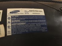
My samsung tube (A68QCP891X001) has a white/blue label, not red. Different tube maybe:
tubelabel.jpg
The Horizontal wires and connector of the "adapter" were crusty and discolored but not burnt or melted.

A quick update on ym troubleshooting.
Simply reconnecting the yoke as suggested: no change
After that, I tested the HOT again out of circuit and it still tests ok, along with a bunch of diodes and other transistors which all seem to test ok.
I am tempted to replace the vertical IC to see if there is any change but I hate throwing parts at a problem.

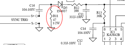
Found a crusty looking 47 ohm resistor (R11) hanging off of a KA3842B which sounds like a PWM controller.
It still tests ok, but I will replace it. The other surrounding components test ok.
R11 hangs off of a loop of wire (labeled Sync Trig S+ and S- here) that is wrapped around the ferrite on the flyback so maybe it's a problem?:
Capture.PNG


Pulled the flyback to inspect once more and noticed that there are some cracks visible that I didn't notice the first time around as it otherwise looks fine.
It's tempting to jump to conclusions but It's hard to say. Don't have any corona dope so I put some kapton tape over it to see if there is any change: no change
You can see the S+ / S- wires mentioned earlier in the photo (white wires) that run inside of shrink tubing
flyback.jpg
 
Last edited:
Even if the exterior plastic is cracked there is still insulating potting compound behind that. You can certainly throw something around the outside though maybe not a bad idea.
 
Is it not true that the flyback resonates
amd that the ferite actually brakes ..

I would be inclined to imagine the flyback
Is aching through those cracks ..
That arching can cause other issues
Including shorting the windings i. The flyback
 
Its very possible. I had a Weiya M3129DB where the flyback arched out from the around the anode wire then jumped onto the metal clip to the ferrite core and then jumped off onto the top of a capacitor and blew the capacitor up.

Look really closely around the flyback if you suspect it to be arcing out the flyback its self there is usually a pin sized hole or scorching left from the event.

I was just saying that cracks in the exterior plastic alone may not cause the fly back to arc since the potting compound should also be insulative .
 
Checked an incredibly buried known working tube. Probed red and blue on the yoke connector and got .6 ohms.

6B87B4FA-BEA4-431E-AB98-F24638E4951A.jpeg

2E222977-865F-4DC2-98ED-1F9D931DA1D5.jpeg

D671403E-FDBD-46B7-87B3-EC30CD532329.jpeg
 
Thanks for the yoke reading @310Imports. I guess my yoke may be alright after all, which is a relief.

I replaced the original 2SC5144 HOT with a FJL6920 (supposedly compatible according to the internet) along with the crusty R11 and now have picture, but it's "messed up" for the lack of a better term. The only difference I could find while testing the HOT and the replacement is the value listed as "B" on the meter which I think is the gain?
Original 2SC5144 is around 4, and the FJL6920 is almost 26. I don't have a spare 2SC5144 for to test with vs the FJL6920 so I don't know what to expect from the 2SC5144.

I swapped the resistor and the HOT at the same time so I have no idea which of them brought it back.
I could swap the HOT back to see what happens but if I don't have to, I won't.

Of course, I didn't dare run it for more than a couple of seconds to capture this so troubleshooting will continue.
Enjoy this 1990s internet style gif of what it does as of right now:
output.gif


What it should be displaying is the backup ram error screen of my broken mvs that I use for basic testing, but the picture is tripled up at different sizes and positions and displayed as a flickery mess.
As was pointed out earlier in the thread by @GeekMan1222, maybe other components could have been taken out when whatever initial failure occurred.
Any guesses?
 
I promised myself I wouldn't work on this anymore this weekend but I couldn't help myself.
Replaced the Vertical IC (TDA1675A) and now have:
IMG_8114.jpg

The blurriness is due to incorrectly set flyback focus, and the color fringing is due to me messing around with the yoke and ring assembly while troubleshooting what I incorrectly thought was a failed yoke.
Really relieved to finally have this back up and running.
I still don't like those cracks in the flyback and will be searching for a replacement though.

Anyway, as a summary reference, I ultimately ended up replacing the following to get from shutdown back to displaying a proper picture:
R11: 47ohm 1/2W Resistor
IC8: TDA1675A Vertical IC
Q36: 2SC5144 Horizontal Output Transistor

Big thanks to everybody that helped out!
 
Well it hasn't blown up again yet, but I get this strange side to side waviness and tearing that comes and goes.
A cold start will show it for maybe 20 seconds, then disappear, and then reappear again after maybe 5 minutes or so of being on.
It didn't do it before this whole ordeal. Where should I direct my attention to?

output.gif
 
Check the components in the horizontal block and maybe around the input.
I have some random notes I left in one of my folders about the Makvisions MAYBE its helpful to you but idk.

I dont normally share alot of notes because I barely take them to begin with sometimes LOL and I think I got most of these notes from SOME where on the internet idr where except for a fix note I made.

Its mostly involving the vertical stuff. I would check values on some of the mylars for input and around the horizontal block your jitter looks to be horizontal in nature


------------------------
Makvision M3129DB1 Notes:


Mylar Caps in Vertical Block M3129D

C56 (Vertical IC Ramp Generator, capacitor A)
0.1 uf 100v

C57 (Vertical IC Ramp Generator, capacitor B)
0.1 uf 100v

C59A (Vertical IC regulated supply voltage, ground coupling?, capacitor)
104 100V


C63 (sync input, smoothing? capacitor)

0.1J 100V
0.1 uF

C66 (Vertical IC Osscilator Capacitor, its value is used to
help shape the vertical oscillation signal)

0.33J-100V
0.33uf


C67 (Vertical IC power amp and drive output for yoke, ground coupling capacitor)
Can fix retrace line issues in the center of screen

0.22J-100V
0.22uF 100V


Replacing Mylar capacitor C67 fixed vertical retrace lines mid way down the vertical deflection raster.
(EG jittering lines unevenly spaced in the middle of the screen. )
 
I may even go the PF chassis mod route, but that would still need a replacement yoke.

Sorry for the sidetrack, but curious about this. IIRC, dewman's guide for a PF swap doesn't involve a yoke swap... are you saying that it is possible to use a PF chassis with the Samsung tube if you swap the yoke with the one from the PF? Sorry if I remember wrong about dewman's guide mentioning a yoke swap.

Reason I ask is I happen to have a spare PF yoke and a chassis salvaged from a tube with a damaged shadow mask... :)

Thanks!
 
That stupid yoke adaptor!
Mine has done the same thing but it burned it to as it shorted !
Glad to see looks like it’s all sorted now,
👍
 
Sorry for the sidetrack, but curious about this. IIRC, dewman's guide for a PF swap doesn't involve a yoke swap... are you saying that it is possible to use a PF chassis with the Samsung tube if you swap the yoke with the one from the PF? Sorry if I remember wrong about dewman's guide mentioning a yoke swap.

Reason I ask is I happen to have a spare PF yoke and a chassis salvaged from a tube with a damaged shadow mask... :)

Thanks!
I couldn't find the chassis swap guide but my understanding is a yoke swap is *not* required, you just have to add a focus wire, and change the neck connector on the neck board of the PF chassis. I believe @adgenet is looking for some high voltage wire to add the additional focus wire if anyone has some they can spare.
 
Last edited:
The way I understood the pf chassis swap is that you perform the modifications, then it simply plugs into the Wei-ya Samsung Yoke and tube (with plug adapters of course).
As @310Imports says, I've been messaging people looking around for some high voltage wire for the focus wire to try this out.

I'd still like to fix this chassis though, as I hate having broken stuff lying around.
I checked out the caps listed in the notes from @GeekMan1222 but they all check out ok, though in all fairness, it's vertical stuff which looks fine anyway.
I will move on to check the horizontal section soon and update the thread.
 
Back
Top