I whipped this up just now, check it over and see if I made any mistakes. I noticed in my KiCad footprints, that none of the included SD card footprints have a pin 13. Also, in the referenced link, there is a schematic where I believe the pin numbering might be wrong on the SD card. It seems to skip over pin 13 and has a pin 14.
So I was good up to pin 12, then I hit discrepancies in Kicad and the referenced schematic with pins 13 and 14.
If you need any changes let me know and I will see what I can do
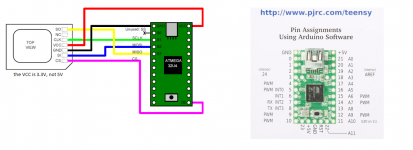
1. The voltage issue is really not resolved at all - It just taps the power from the Teensy which is probably 5v. I can put a little voltage reg IC that will go 5-> 3.3 to fix this issue. Wasn't sure if there was a way to run the Teensy on 3.3v and solve it that way.
2. That was the first time using that full sized SD card footprint, but I believe I got the SD opening on the edge of the PCB.
3. I can swap out JP1 for a pin header rather than solder pad.
all of that sounds good. yeah there needs to be some kind of regulator to 3.3. also i can show you how there is only 7 of the typical sd pins on these,
PS - I am choosing not to pour a ground plane on this board as that connects to the 4 corner pads (pin 12) to the ground pins on the SD card (pins 3, 6). I figure if you need to isolate the 4 corner pads (pin 12) from ground, you could easily break a trace or two - if there is a ground pour, you'd have a much harder time isolating the corner pads if needed.
TE-2041021 is good but it needs 180 degree flipped to edge so sd can be slide in. this is sweet looking besides that. can you make some mounting holes/screw holes please
Mouser shows lots in stock of all the different dash versions, so I think the SD card slot is good, no? It is the larger standard SD slot, so I wonder if most the larger SD slots are NRD (not recommended for new designs) since its the older size/style.
You're right on the orientation, I will flip it 180 degree. Mounting holes should be no prob.