@winteriscoming talk to @Mitsurugi-w Please.
You are using an out of date browser. It may not display this or other websites correctly.
You should upgrade or use an alternative browser.
You should upgrade or use an alternative browser.
- Thread starter winteriscoming
- Start date
I can help with kits but I'm having a hell of a time getting any arduinos I program to work with the pcbs for some reason. Worked a year and a half ago and now the new ones I program don't work while the ones I programmed back then do. Ugh.
Are there hardware variations? I've run into issues where bootleg Megas use some similar but not exactly the same chips that has resulted things not running the way they should
winteriscoming
Champion
I've had pretty consistent results with OSOYOO branded Megas. I don't have much experience with others, but I did recently buy a nice-looking orange one branded as IDUINO that seems to be working fine.
There could be Arduino IDE variations. I'm still using version 1.6.12.
I have posted a compiled binary that can be loaded up with XLoader to eliminate any concerns with compiling the code. I just tried it on my IDUINO branded board, and it works.
There could be Arduino IDE variations. I'm still using version 1.6.12.
I have posted a compiled binary that can be loaded up with XLoader to eliminate any concerns with compiling the code. I just tried it on my IDUINO branded board, and it works.
winteriscoming
Champion
Here's the orange IDUINO that I have only done minor testing with:I had the same issues as Mitsurugi. After trying several Arudinos with no luck I moved forward. I'll buy those that you mentioned and try again. Can you please provide a link?
https://www.amazon.com/iduino-Atmeg...F8&qid=1541698353&sr=8-1&keywords=iduino+mega
Edit: Actually, I'm not seeing the OSOYOO versions anymore... The one I linked is a different brand I haven't tried.
Prices seem to be all over the place. I'm pretty sure I've gotten those OSOYOO ones for $9.99 in the past.
Last edited:
winteriscoming
Champion
I updated the post above. The one I thought was the OSOYOO version wasn't, and I can't seem to find the one I've bought before on Amazon anymore.
 let me know if you find the exact one. The solution definitely will be better if it has the arduino integrated into one single PCB.
winteriscoming
Champion
There have to be a couple other known working Megas...
@freddiefiasco, you've got a V2 board, right? Any feedback on the brand of Mega 2560 you've had success with?
@Darksoft, any luck uploading the compiled code to one of the Megas you have? Is nothing working (as in no display or other visible signs of life like a message over the usb serial connection?) or it just won't pair with a game?
@Mitsurugi-w, same questions for you. Does the compiled code work on your newer Megas? What's not working, and are the newer ones a different brand than the one you had working a year ago?
winteriscoming
Champion
It would be prettier, for sure, and can help with consistency in parts/quality, but I still like the idea of utilizing off-the-shelf Megas because if someone burns one up by reversing polarity or whatever, then it's a $10-15 replacement to swap out instead of having to invest in a whole new custom I/O board.The solution definitely will be better if it has the arduino integrated into one single PCB.
If I were producing it for sale on my end, I'd likely keep with the same format of the MEGA JVS being a Mega2560 shield board. It's cheap, it works (for me anyway) and it is going inside my arcade cab, rarely to be seen, so it doesn't matter to me if it ends up being an ugly stack of boards.
If you get a V2 working and decide you want to invest time/resources in a redesigned single board solution with expanded functionality, I will welcome it with open arms.
")
You might replace the rs485 module and simply use an rs485 driver chip and the additional components (a few capacitors and resistors).
I know these modules are cheap, but the chips will be available longer than those boards which might change form factor over time.
There are different manufacturers making those chips and they are pin compatible with each other. Some have a 5V supply and others a 3V3 supply voltage.
I know these modules are cheap, but the chips will be available longer than those boards which might change form factor over time.
There are different manufacturers making those chips and they are pin compatible with each other. Some have a 5V supply and others a 3V3 supply voltage.
winteriscoming
Champion
That might not be a bad idea, but probably the same argument could be made for the micro SD module. They're both relatively simple modules, so worst-case if staying with them would be designing pin-compatible replacements if it's ever needed, or redesign the board at the time they're no longer available. In both cases, I think the modules are currently way cheaper than the sum of their parts for the small quantities I'd be buying them in.You might replace the rs485 module and simply use an rs485 driver chip and the additional components (a few capacitors and resistors).
I know these modules are cheap, but the chips will be available longer than those boards which might change form factor over time.
There are different manufacturers making those chips and they are pin compatible with each other. Some have a 5V supply and others a 3V3 supply voltage.
Price wise, the difference will be marginally. You can sell blank pcb's as diy.
You could add a component list with the order numbers from some of the major component distributors like RS / Farnell / Mouser just to name a couple.
Doing so, anyone interested can order the needed components as there are many sources.
If I have to order some chinese rs485 pcb, it becomes more complicated as delivery times can go up to 4 weeks and I have to buy from some unknown chinese distributor or on ebay.
Don't get me wrong. I use such boards as well during prototyping. The arduino board is a different beast. The official ones are sold way to expensive, and now I read that some clone's don't work properly.
You would expect if the board uses the same atmega 2560 microcontroller, it should work, unless the boards are defective?
I do have a chinese laser engraver I use to make pcb's based on a clone arduino, and I had problems updating the code as I needed a non standard uploader program. This could mean that they have some different bootloader not compatible with AVRDUDE (the uploader the arduino ide uses) Maybe the solution is as simple as uploading a new bootloader using the spi port and another arduino as programmer. (And maybe it isn't and the boards simply don't work) A blank pcb likely will survive shipping in a bubble wrap enveloppe so it can be shipped cheap.
winteriscoming
Champion
I received my V3 boards today! Limited testing makes me think they're working fine.
I enlarged the board to accommodate the new headers and traces needed for those, and moved the micro SD module and some optional headers a bit to give them more room. I don't much like software subscription models, but I went ahead and subscribed to the lower tier of Eagle on a monthly basis since this project started in their free version and I needed the first pay tier to get the sizing I wanted. I like that I kind of know my way around the software now, so I may drop and pick up the subscription as my projects demand it.
I enlarged the board to accommodate the new headers and traces needed for those, and moved the micro SD module and some optional headers a bit to give them more room. I don't much like software subscription models, but I went ahead and subscribed to the lower tier of Eagle on a monthly basis since this project started in their free version and I needed the first pay tier to get the sizing I wanted. I like that I kind of know my way around the software now, so I may drop and pick up the subscription as my projects demand it.
winteriscoming
Champion
I'm not opposed to integrating the parts of the modules into the main board if through-hole options are available. I do still want to stick with through-hole components for easy DIY for those with lower soldering skills.Price wise, the difference will be marginally. You can sell blank pcb's as diy
I have found schematics for the MAX485 and Micro SD modules.
I'm seeing this for the MAX485 module, which isn't bad:
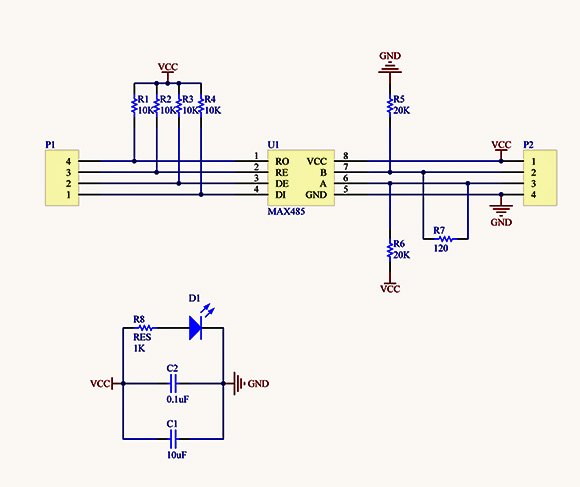
That lower section has the power LED which can be eliminated, but I'm not sure what the function of the 2 capacitors from VCC to GND serve unless their placement within the upper schematic is important for reducing EMI. I'm seeing something similar on the MicroSD module.
I found the schematic for the SD module I'm using here. It uses a level shifter and 3v3 voltage regulator. I can probably ditch the regulator and pull 3v3 from the arduino, and there are probably through-hole level shifters that can be used. The challenge is finding an acceptable MicroSD (or even standard SD) slot. I'm not seeing through-hole variants except as modules, and there is a lot of variation in options on modules.
The OLED display is probably just going to need to stay as-is - it probably doesn't count as a module in this case:

At any rate, I'm not sure when/if I will get around to integrating these parts.
winteriscoming
Champion
Here's a pic of the progression from V1 to V3:

The 10uF and 0.1uF are decoupling capacitors. They stabelise the voltage as the chip it's current draw isn't constant during operation. The value of these components is not an exact science. Maybe in the datasheets of maxim they might recommend those decoupling capacitors and their minimum value. They also suppress noise on the voltage rails that could otherwise cause EMI interference.
For the sd card 3V3, you need to know how much current the arduino can deliver on it's 3V3 and also if it's sufficient for most brand of (micro) sd cards.
You shouldn't be to scared about smd soldering. As long as it's not fine pitch, it's not that difficult. Smd components like resistors are usually cheaper than their wired equivalents.
Also check your arduino 5V rail. If you use 12V to power your JVS, the arduino will lower it to 5V using a linear? regulator. Those things also have a maximum current.
As original JVS boards have both 12V and 5V, you probably use the 5V to power your arduino so that it isn't an issue.
The 4 10K pullup resistors on the max485 likely aren't needed either as you can enable pullups in software on the arduino ATMEGA.
The /RE (receive enable) is maybe not needed. If you permanently enable the receiver, you will also receive the data you are sending yourself. Not sure if your program expects it to be like that or not.
The /DE (drive or transmitter enable) is needed as only one device can transmit on the bus. After that, the bus needs to be released to see the data from other devices on the bus.
Last edited:
winteriscoming
Champion
I'm not against SMD, personally, and would like to start utilizing SMD in pcb projects, but I don't think it's in the skill set of most amateurs at soldering.You shouldn't be to scared about smd soldering.
Currently the display, MAX 485 module, SD Module, and analog inputs are powered by the Arduino's 5v (or 3v3 depending on jumper implemented to accommodate Arduino DUE). I suppose the 5v is also driving the output and SENSE MOSFETs, and there would likely be some draw from all the internal pullup inputs. I do actually power the arduino with the JVS 12v since it seemed like that would be safer because it allows for a range of acceptable voltage levels whereas the direct 5v has stricter requirements. I didn't want a JVS 5v adjusted out of spec to burn up the board. So far I've had no apparent issues with overloading the Arduino's regulator, and I can even successfully powered it via USB (lacking JVS 12v and 5v for JVS outputs).Also check your arduino 5V rail. If you use 12V to power your JVS, the arduino will lower it to 5V using a linear? regulator. Those things also have a maximum current.
As original JVS boards have both 12V and 5V, you probably use the 5V to power your arduino so that it isn't an issue.
I don't know... I'm a novice at all this, so I'm probably not doing everything correctly. Hopefully I'm at least not starting fires.
