What's new
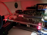
With Jassin's approval, you got yourself a stellar setup.
You know I'm just hot for all dem HAS+OSSC+OLED/LCDzzz man. <3
IMO a DS multi+HAS+OSSC is the most amazing combo of a DIY electronic hobbyist community collaboration in action!
don't forget to add Jasen's Panzer wireless sticks to the chain:)
 
With Jassin's approval, you got yourself a stellar setup.
You know I'm just hot for all dem HAS+OSSC+OLED/LCDzzz man. <3 IMO a DS multi+HAS+OSSC is the most amazing combo of a DIY electronic hobbyist community collaboration in action!
don't forget to add Jasen's Panzer wireless sticks to the chain:)
I recently completed my wireless stick hackjob of a project that involves a UD-USB decoder to miniKade+ Controller Adapter connects to a Wii Mote acting as a Wii classic controller. Then using 8BitDo receivers to connect the 'Wii Mote w/ Classic Controller' to play wirelessly PC/NES/SNES. Since I think A the classic controll with wii mote is supproted with a Cronus MAX, this thing can theoretically turn your usb stick into a wireless one for the modern consoles.

It's a mess of hobbyist PCBs, but it beats having extension cords to the PC across the living room to the bedroom.
 
Last edited:
HAS 3.0 with OSSC on 50” lcd tv, the result is really great. Look really sharp with scanline and the audio so great too.
I fully approve of this setup! :thumbup:
Fantastic picture too! 8o
THX !!
And going to test some sega model 3 board when I have time. Really want to see how it show with OSSC and of course the greatest HAS to make home arcade setup easy !! :thumbsup:
 
Yup totally PnP to a xRGB mini, same pinout just grab a shielded 8-pin mini din cable.
If you want to use a OSSC you'll need a 8-pin mini din to Euro SCART cable.
I'm assuming we'd need a cable like this then to do HAS → OSSC?

https://retro-access.com/collection...-cable-pro-coaxial-multicore-for-switch-boxes


UPDATE: I ended up going with the etim cable RGB linked just below this post with no problems after some simple soldering. Others have mentioned issues with the retro-access.com cable.
 
Last edited:
Hey,

No, HAS outputs only RGB video (R'G'B+CSync), this cable won't work. What you need is an RGB to Component transcoder. Please refer to the HAS instruction manual for more details (8pin mini DIN pinout etc.).
 
  • Like
Reactions: ULi
Received mine.
Thanks again for making this amazing peace of hardware alive !
 

Attachments

  • IMG_20171120_105004.jpg
    IMG_20171120_105004.jpg
    82.1 KB · Views: 323
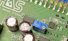
Since the HAS V3.1 has no potentiometer for sync, does that mean it won't have any way of adjusting the horizontal position of the image on a PVM, e.g. to fix F3 being shifted to the side? I was looking forward to that feature, so pretty bummed if that's the case.
 
@udongein - That's correct, I decided to remove the pot. The horizontal position adjustment worked only to some extent and I considered it a side effect really.

If you really need it, the EL1883 has the same footprint as the ISL59885 used in the V3.1 and is almost a drop-in replacement, so it can be swapped. Aside from IC replacement, the mod would just require two extra components - a 100nF ceramic capacitor (0603 package) and a 1M multi-turn potentiometer. The potentiometer could be glued to the HAS PCB, or even soldered to the CN4 port holes (you'd just need to make sure to cut a few traces that go to the CN4 port, and route a wire to the EL1883).

37851643804_b3fb49306b_m.jpg


A less invasive approach would require a custom PCB for the EL1883 + pot, which could then be plugged to the CN6 connector, or a combination of CN4 and CN6.

The most versatile solution however, is adding an Extron RGB 203 Rxi unit to your setup. It's inexpensive and allows to tinker with both the vertical and horizontal screen position.
 
Last edited:
@udongein - That's correct, I decided to remove the pot. The horizontal position adjustment worked only to some extent and I considered it a side effect really.

If you really need it, the EL1883 has the same footprint as the ISL59885 used in the V3.1 and is almost a drop-in replacement, so it can be swapped. Aside from IC replacement, the mod would just require two extra components - a 100nF ceramic capacitor (0603 package) and a 1M multi-turn potentiometer. The potentiometer could be glued to the HAS PCB, or even soldered to the CN4 port holes (you'd just need to make sure to cut a few traces that go to the CN4 port, and route a wire to the EL1883).

37851643804_b3fb49306b_m.jpg


A less invasive approach would require a custom PCB for the EL1883 + pot, which could then be plugged to the CN6 connector, or a combination of CN4 and CN6.

The most versatile solution however, is adding an Extron RGB 203 Rxi unit to your setup. It's inexpensive and allows to tinker with both the vertical and horizontal screen position.
could you give us more information about the custom PCB for the EL1883 + pot solution.

I think this is the best solution.

thanks
 
What I meant, was that one would need to design and produce a custom PCB for this. You just follow the schematic for EL1883 from the datasheet, but instead of the fixed resistor connected to Rset (pin #6) you use a 1M multi-turn pot configured as variable resistor. CN4 and CN6 are described in the HAS instruction manual.
 
thanks.

perhaps one of the tech advanced owners here is willing to do this.

would be great
 
Back
Top