What's new

Philbee90

Student
Joined
Oct 30, 2016
Messages
63
Reaction score
26
Location
Ireland
I've been using the yellow wire on the gpu fan to hard reset the Naomi 2 but I've come across a Naomi 2 that is not reliable when using the gpu fan/fans to hard reset. Just wondering if anyone knows the correct point on the board on force a hard reset. Any help is appreciated :thumbup:
 
^that^

Would be cool to know if there is a point that could be shorted to gnd or something to make the naomi reset.
 
kind of related but not. dreamcast has a reset pin on the bottom side of its board.
 
  • I've done the dreamcast reset mod before and it does work (I asked mnemo to incorporate the use of it into his USB gdrom board to save power cycling the DC to change games). Its what leads me to believe that there may be one on the Naomi somewhere.
 
Just to be clear on the issue, I have a dual channel relay that interrupts the feedback (yellow wire) from both gpu's. When I select a game using piforce web, the relays switch, opening the feedback wires on both gpu's, the Naomi screen goes blank and randomly stays blank and randomly reboots correctly. Everytime on powerup the Naomi starts without issue, it seems to be only linked to the reset technique. I've tried another Naomi 2 with the same pi/relay setup and the reset works Everytime
 
All or most PCBs have some kind of watchdog which checks the voltage level. If it's too low it will reset the whole system. This is how we did the reset in STV.

IT's usually a 8 pin small SMD. If someone can post pictures of all such a chips in the Naomi, I could pinpoint which one it is. If you have schematics, even better.
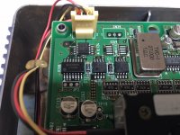
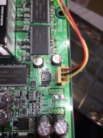
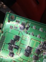
Here you go:

IMG_6402.JPG
IMG_6409.JPG
IMG_6408.JPG

Datasheets :)

View attachment MB3773.pdf

View attachment MB3771.pdf

Seems like each fan has a 3773 watchdog timer ic. So I guess we can short a pin to gnd on it to have the naomi reset?
 
Last edited:
It'd be nice if such a thing existed on the Net-DIMM board, that would allow all of the equipment for net-booting to be completely separate from the main board.

If that were possible you could then mount a Pi3 inside the dimm board for a super clean setup.
 
It'd be nice if such a thing existed on the Net-DIMM board, that would allow all of the equipment for net-booting to be completely separate from the main board.

If that were possible you could then mount a Pi3 inside the dimm board for a super clean setup.
That would be cool. I mean the netdimm has to issue a reset command to the naomi somehow.

I wonder if the the wifi on the Pi3 will still work inside the case? Since the case is basically "shielded" all around with conductive paint/finish?
 
All or most PCBs have some kind of watchdog which checks the voltage level. If it's too low it will reset the whole system. This is how we did the reset in STV.

IT's usually a 8 pin small SMD. If someone can post pictures of all such a chips in the Naomi, I could pinpoint which one it is. If you have schematics, even better.
Here you go:
IMG_6402.JPG
IMG_6409.JPG
IMG_6408.JPG

Datasheets :)

View attachment MB3773.pdf

View attachment MB3771.pdf

Seems like each fan has a 3773 watchdog timer ic. So I guess we can short a pin to gnd on it to have the naomi reset?
Thanks Erick,

You just need to connect pin number 8 which is /reset to God. Use a resistor of at least 100 ohm just in case.
 
Thanks Erick,

You just need to connect pin number 8 which is /reset to God. Use a resistor of at least 100 ohm just in case.
Sweet, so a common 1/4w 220ohm resistor should do? So pin 8 to gnd thru resistor, whos testing this out? :)
 
I wonder if the the wifi on the Pi3 will still work inside the case? Since the case is basically "shielded" all around with conductive paint/finish?
That's a good point. maybe run an external antenna into the un-shielded battery area? https://www.dorkbotpdx.org/blog/wramsdell/external_antenna_modifications_for_the_raspberry_pi_3
or worst case you could mount the Pi external to the metal portion of the DIMM case, it'd still be one unit just bulkier.
Nice, could add an external antenna, should not look too bad. gonna try to test fit the pi inside the netdimm hopefully this weekend. Might need to 3d print some type of support system for it.

So, would still need to find a 5v source on the netdim to power the pi, but I guess there is enough clearance between the naomi and the netdimm for running a few wires for power and the reset circuit if needed.
 
Might need to 3d print some type of support system for it.
If you have something in mind let me know. I've got a few Pis and net dimms kicking around to take measurements.
another option would be a 3d printed lid that replaces the metal one, adds space for the pi and integrates the LCD there.

So, would still need to find a 5v source on the netdim to power the pi
I would think there is 5V available somewhere in the Net-DIMM no? the only question would be if there is enough juice to run the Pi without over drawing. I would think pulling from whatever 5V source is closest to the connectors would be the best bet.
 
Back
Top