You are using an out of date browser. It may not display this or other websites correctly.
You should upgrade or use an alternative browser.
You should upgrade or use an alternative browser.
- Thread starter RealMFnG
- Start date
I been wanting a nice voltage/video test PCB. Keen to see what you’re cooking @ic3b4llRegarding the RGB test screen... Stay tuned, it's in the works. *Suspense*
Put the order in for the final prototype PCB. Added in a couple of other projects with the order to save on shipping. This revised JAMMA adapter, also based on Frank's work. And another personal project. Guess what this one does:

Last edited:
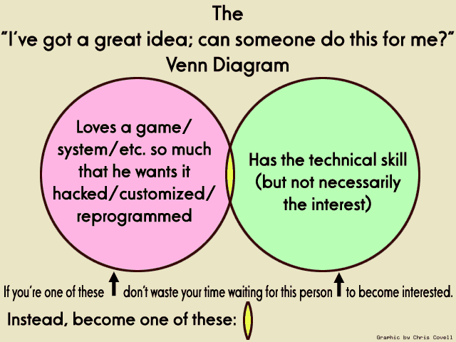
It's coming to fruition. It has been fun too. Learning how to use tools to put into motion the ideas in your brain has been a joy. @Hatsune Mike was spot on with his Venn Diagram (except for the relative volume of ppl in the green bubble).
Working PCB has been finalized and ordered. Added standoffs to the design to prevent flexing as the switches are depressed. BOM finalized & parts have been ordered too. Assembly and testing after that. Footprint is closer to the size of a dollar bill now. If it works, I may leave it as is. Only other idea I am toying with is adding in SMD LED's for button signal indication. Hesitant to though as that adds to the complexity of assembly and not everyone can do that. Plus costs go up. Also, it might be a bit too much FPS (Fancy Play Syndrome).Every time there is a "X Multi is possible?!" thread
Also, I am using the 2x10 MC header for external controls. But realize lots of dudes have SuperGun Neo Geo controllers already. Probably will necessitate creation of a single daughter board allowing for controls of that type. Want it to be usable and made by a user for the user. The @Arthrimus approach.
View attachment 41574
I totally screwed up this run of PCB's. I mapped the signal lines to the wrong leads on the tactile switches. So I didn't even assemble these PCB's. $7 I'll never see again.
Anyhow, I've decided I am going to redesign this taking into account the feedback from @brad808. But will be taking it a bit further because as a personal project, there are a few things I need to solve for. I think I can add 2-3 other functional purposes for the redesign I have in mind.
Anyhow, I've decided I am going to redesign this taking into account the feedback from @brad808. But will be taking it a bit further because as a personal project, there are a few things I need to solve for. I think I can add 2-3 other functional purposes for the redesign I have in mind.
So based upon recommendations from @brad808, which are to prevent the loss of connectivity in a test bench scenario, the JAMMA edge connector will be moved to a separate daughter board.

In thinking about the daughter board, I figured I could solve for some other personal needs. So here are additional applications the daughter board serves:
In thinking about the daughter board, I figured I could solve for some other personal needs. So here are additional applications the daughter board serves:
- Can be used as a JAMMA extension cable (w/an edge adapter which I'll cook up too)
- Can be used to hard wire a JVS cab for JAMMA application
- Can outright be used as an improved JAMMA harness
- Works with CHAMMA
- Works with Sega JVS I/O's w/button 4 & 5 on edge connector and 6 routed via harness
- Shall have a slide switch which allows for:
- JAMMA audio to be attenuated to line-level dual mono through RCA output
- MVS stereo line-level output through RCA's
- Attenuation based upon this circuit
- Shall have a slide switch for CHAMMA connection
- Shall have the ability for -5V to be provided from a switching PSU, or from a Negatron
- Solder jumper blob selectable
- Shall be able to accommodate voltmeters of slightly different sizes at close to the same form factor w/access to calibration pots
- JAMMA signal lines uses the Hirose DF1B connectors (AKA CPS2 Kick Harness connector), which most of us snobs in this hobby should have parts for and making the parts sourcing easier
Last edited:
LittleMegaGamer
Student
Hi, Do you still have this test bench? I would like to see some more pictures please (about wiring).
Also, Is the green-yellow cable that goes from the power distribution to the iso-transformer the "Live" cable or "ground"?
Thanks
