I posted about CRTs before, and I will say again that I am unfamiliar with them. I hope that if any part of my post is wrong, someone will correct me.
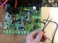
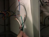
That said, I would like to say that from looking at the schematic, both lines pretty much immediately enter a bridge rectifier, so worrying about Live and Neutral shouldn't matter for this application functionality wise, but the configuration of the fuses on the board would be what I would go by for safety.
You want a fuse closest to the entry of Live so that a fault that blows the fuse will leave the greatest portion unconnected and "safe". For this specific example, I would, without having more information, attach Live to the line that has "F1" on it, and neutral to the remaining AC line. The other line has a fuse as well, "F2", but it is slightly downstream of the mystery component "DGC" that sits before the PTC. Without knowing what this is, I would prefer to have Line on the side protected by F1.
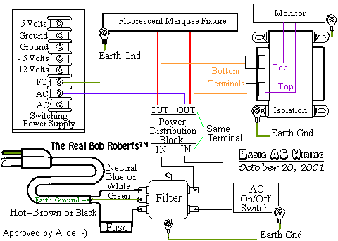
For earth ground, the metal frame of the monitor (as well as other things in a cabinet that are metal like control panels and coin doors) should be connected to a central grounding point somewhere directly connected to the earth wire of your 3 prong plug, but nothing directly on the chassis board since it has no provisions for anything. Do not under any circumstances wire earth to neutral despite both earth and neutral under non-fault conditions theoretically being at 0 potential.
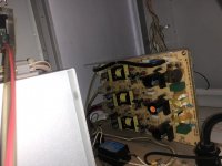
Edit: I needed to look at your schematic a bit more carefully. There are ground symbols littered across the schematic.
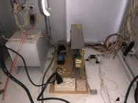
I suspect your chassis screws into a metal bracket / board holder/tray or something.
If so, continuity check one of the grounds in the schematic to the mounting bracket. If it checks out, that's where you want to connect earth.

")