Let's see some pictures of the fix after you test it.
You are using an out of date browser. It may not display this or other websites correctly.
You should upgrade or use an alternative browser.
You should upgrade or use an alternative browser.
- Thread starter The Spaniard
- Start date
xodaraP
Legendary
Your wish is my commandLet's see some pictures of the fix after you test it.

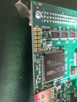
Here is a photo of what the board looked like when I got it - you can see the pad is very well removed from the board as well as broken off from the trace itself. I ended up cutting it out so I could run a completely new wire to replace it.
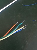
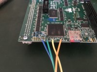
For those of you doing this mod - these wires are cut far too long. You probably need about half this to attach to the pads, having them longer increases the risk of shorts with other components.
I tried connecting the wire directly to the proper pin on the ARM initially, but I found it didn't stay well attached. So instead I cut the original trace as short as possible to the ARM and connected it from there. I left a bit of length in the wire in case I had to route it around components, but it ended up being a bit long. Realistically I could cut it shorter and reconnect it, but at the same time I'd rather leave it as it is since it's not shorting anything and it isn't hugely noticeable.
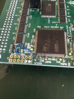
I then routed the wire that would normally be connected to the missing pad to the through hole that is now connected, I wrapped the new wire jumper around the outside of the through hole and then put the board wire through the hole before soldering it on the bottom side.
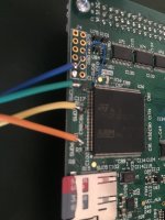
I then used some isopropyl alcohol to clean things up as there was a bit of burnt flux residue around and I wanted to clean it up a bit. The other 3 wires are also connected. I realised after I started it up the first time and it didn't start (gave me a quick black screen then turned off but LCD/multi were still running normally) - I accidentally switched around 2 of the wires (yellow and orange in the photo) so I removed them and resoldered them down. Always double check your wires are connected to the correct pads!
Then I powered it up and got this screen......
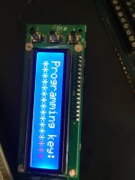
Then
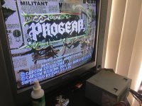
Success!
Other than the little bit of extra wire I think it's turned out very well. Happy to say it's back to working perfectly. I changed games a couple of times to confirm it's all working properly as well.
Last edited:
xodaraP
Legendary
Paging @The Spaniard - you're good to go it looks like
Don't ask Darksoft to solder for you. It aint pretty. Trust me.Thanks Darksoft, it's not as nice as your and Mitsu's work but I'm happy to say it's fixed and I don't want to mess with it to try and make it cleaner

The Spaniard
Professional
Thanks xodaraP really nice work there in fixing that mistake.Paging @The Spaniard - you're good to go it looks like
Appreciate all the help from everyone here.
When I have to do such repairs, I usually also fix the wire to the pcb with a small drip of loctite after everything is tested. (Not on the soldering but somewhere nearby preferable on an area without other tracks.) This prevents the soldering and the small pcb track from being mechanical stressed even when the wire is accidentally touched and eventually bent a little. In this case it was obviously difficult to find such a spot.
We all make silly mistakes. I've made plenty myself but always learn from the experience and try to not nake the same mistake twice.
Kudos to @xodaraP for putting his hand up to help out. You're a stand up guy and have helped me out a ton as well.
Great community here. Nice to see everyone treat each other so well.
Kudos to @xodaraP for putting his hand up to help out. You're a stand up guy and have helped me out a ton as well.
Great community here. Nice to see everyone treat each other so well.


