What's new
I have a feeling that the Jamma video signal is disconnected. My chassis only ever worked through the VGA cable. I never actually tried 15khz, only 24 and 31khz then it died.
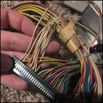
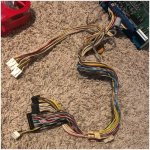
This was my thinking and why I posed the question about the IO board.... I'd be following the wiring from the JAMMA edge RGBs lines back to the chassis to see if there's a disconnection somewhere.
 
Here is a pic of the CN10 connection. From what I could gather, all of the cut wires were originally connected to the kick harness.

The wiring guide says “to cabinet output harness”

I’m going to spend some
time reconnecting these wires to their original source. After that, I’ll post an update. If that doesn’t solve anything, my bets are on a problem deeper into the chassis.
 

Attachments

  • 13778B6E-3177-48C4-99DA-B81776EC28DA.jpeg
    13778B6E-3177-48C4-99DA-B81776EC28DA.jpeg
    318.1 KB · Views: 235
According to the wiring guide linked earlier, CN5 is where the monitor connections are (I think this is inputs) so check that too.

CN10 could well be the outputs, I wonder why they've been cut.
 
Ok so follow the wires back from the monitor chassis and see where they go and if they're connected properly
 
Had time today to jump inside the cab again. I cut a lot of zipties to try and find where the monitor connections connect and checked all connections to make sure they are secure.

So the line comes from the chasis and splits off into two molexes that live under the bezel. From there two red wires split off and I believe they end up at the power switch in the CP. The rest flow down into CN10 on the Blast I/O. From there, I can only assume they come back out through CN5 and through the jamma harness to the edge.

Seperately, back at the chassis, a set of wires lead to the breakout board. The VGA cable is also connected directly to the chassis. Unfortunately, at no point did I bump into any dip switches anywhere.
 
I have a feeling that my jamma harness may be the wrong one for the job I am trying to do. On the blast city wiki, it mentions a model 3 loom for jamma and a 001 loom for JVS. I have the 001 hooked up. Am I possibly going to need the Model 3 Loom to run rgb off jamma?
 

Attachments

  • 15D424E8-B40C-4A8E-B791-91851034AF15.jpeg
    15D424E8-B40C-4A8E-B791-91851034AF15.jpeg
    531.8 KB · Views: 255
Remember that some jamma harnesses have the(rgbs+video ground signal) wires directly to a db15 connector. This allows someone to plug in an old jamma board in while still utilizing the db15 connection that inputs to the chassis. Just an extra thought.
 
Remember that some jamma harnesses have the(rgbs+video ground signal) wires directly to a db15 connector. This allows someone to plug in an old jamma board in while still utilizing the db15 connection that inputs to the chassis. Just an extra thought.
That could work. However, I would also need the connections to the blast io as well for inputs. Does anyone make such a harness, or would I need to frankenstein my own?
 
In the link I added there's a schematic for the rodotron chassis. It is clear from that, that the only RGB connection is via the DB15 VGA connector. If you want to use this with standard Jamma boards you will need an adapter that can plug into this.
 
In the link I added there's a schematic for the rodotron chassis. It is clear from that, that the only RGB connection is via the DB15 VGA connector. If you want to use this with standard Jamma boards you will need an adapter that can plug into this.
That was next on my plan of attack. Already ordered some db15 breakout adapters to try to feed to the db15. I’m sure that’s going to solve things. Thanks for the resources guys. :)
 
Already ordered some db15 breakout adapters to try to feed to the db15
The connector is actually called HD15, not DB15... But everyone just calls it VGA, which is actually only the signal type carried. :S

DB15
0004090_25-ft-serial-extension-cable-db15-mf.jpeg

HD15
2011062086239801_1_.jpg


Anyway, yes wire up the VGA port like you would normally wire VGA.

34bb59ce594772cf008dedb9f57fe8fe.jpg


But when you get to pins 13 and 14 (normally H and V sync on VGA) you will only connect pin 13 to composite sync (leaving 14 empty). :thumbup:
 
Thank you Jassin000! I’m sure I would have screwed up that wiring.

So, progress report:
I bypassed pretty much all of the I/O in the Blast. Used my own power supply to a new jamma loom, and wired up the video connection. Third Strike fired up right away with perfect video. Thanks again everyone! You’re awesome!
 

Attachments

  • DB7AB3CE-23C8-4B42-82C6-D43AB625536A.jpeg
    DB7AB3CE-23C8-4B42-82C6-D43AB625536A.jpeg
    226.6 KB · Views: 234
I found this thread searching for answer to my blast monitor not powering up. I tried to use a multimeter on the power connector to the monitor to see if I even get power coming through and I don't think I am. https://wiki.arcadeotaku.com/w/File:Ms9pinout.png
It even tried to undo the IO board and test out the pins in the back of the CN10 (Cabinet output harness). I do get voltages from there. The monitor did work briefly for about 5 minutes and then shut off. It doesn't seem like it's getting any power. I hear no noise coming from the monitor. Could the harness all of the sudden fail like that? That doesn't make much sense to me. Does anyone have any ideas that I can try to troubleshoot my issue?
 
Back
Top