^agreed!
You are using an out of date browser. It may not display this or other websites correctly.
You should upgrade or use an alternative browser.
You should upgrade or use an alternative browser.
Console JAMMAizer! Easily connect home consoles to your JAMMA arcade cabinet.
- Thread starter Arthrimus
- Start date
The sync stripper and audio amp have now been tested and debugged so this version of the board is going into prototype production.
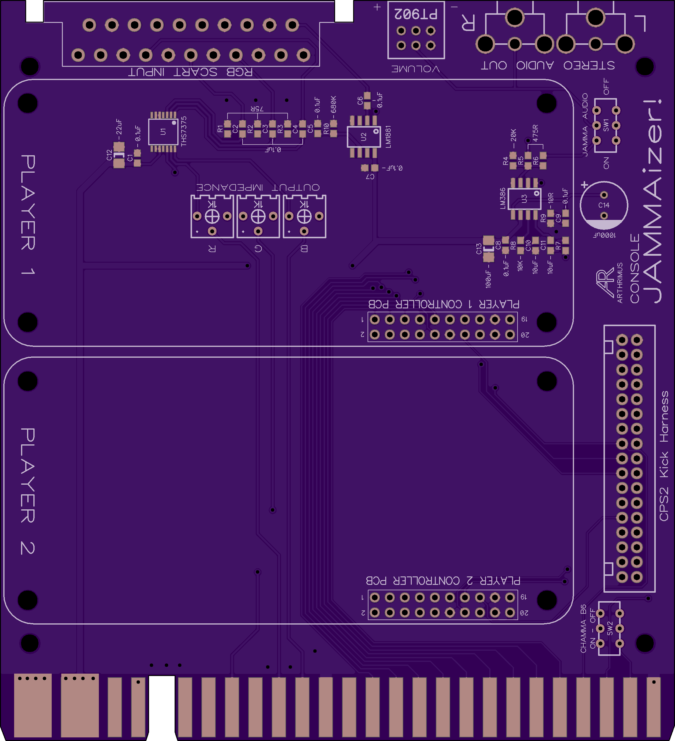
A couple of changes since the last version. I changed the audio output selection switch to allow either STEREO RCA only or STEREO RCA + MONO JAMMA. This way if you are only using STEREO then you can completely disconnect the Mono amp from the audio chain. I've also added buttons 5 and 6 to the JAMMA edge. There is a switch to disconnect button 6 from the JAMMA edge for those who do not have a CHAMMA style loom.
I'll report back once I have my test PCBs in.
This is awesome. What a no bullshit way to solve for the problem.
Regarding my earlier request to add a VGA header on-board, allowing JAMMAizer to be used for MAME use. Don't bother. 1) The footprint of your PCB is so beautifully compact that adding it such a header would detract from it. And 2) after asking TheLastBandit and viletim to simplify their designs and dropping the idea of engineering their own console control modules in favor of simply allowing the user to use MC PCB's, seems rather hypocritical of me to ask you add such a feature complicating further your design.
What can be done instead is:
Alright, here are my questions:
Regarding my earlier request to add a VGA header on-board, allowing JAMMAizer to be used for MAME use. Don't bother. 1) The footprint of your PCB is so beautifully compact that adding it such a header would detract from it. And 2) after asking TheLastBandit and viletim to simplify their designs and dropping the idea of engineering their own console control modules in favor of simply allowing the user to use MC PCB's, seems rather hypocritical of me to ask you add such a feature complicating further your design.
What can be done instead is:
- A separate VGA-to-SCART(male) PCB is created to allow for MAME use
- A separate RGB/VGnd/Sync Terminal Board-to-SCART(male) PCB is created to allow for any other retro video game source to be used with JAMMAizer
Alright, here are my questions:
- What is your power source for each of the onboard IC's
- SCART or JAMMA edge or a combination of both?
- You've made the pass-thru version of JAMMAizer and the EZ Loader MC Cuthulu PCB's freely available
What is your intent for this PCB's availability?EDIT: Nevermind, I see you've made it available on the OSH Park Projects page. Kudos for that!
Last edited:
Well you know I was actually just thinking that it might be possible to add a pin header up near the SCART connector that could allow a daughterboard with VGA and audio inputs to be stacked on top of the JAMMAizer PCB. Kinda like how the HAS does with VGA output. I haven't ever messed with MAME on real arcade hardware so I don't know much about it, but I understand most people use graphics cards with bios hacks or driver hacks to output 15khz RGB. Would you need a sync combiner for H and V sync or do these cards output Csync?This is awesome. What a no bullshit way to solve for the problem.
Regarding my earlier request to add a VGA header on-board, allowing JAMMAizer to be used for MAME use. Don't bother. 1) The footprint of your PCB is so beautifully compact that adding it such a header would detract from it. And 2) after asking TheLastBandit and viletim to simplify their designs and dropping the idea of engineering their own console control modules in favor of simply allowing the user to use MC PCB's, seems rather hypocritical of me to ask you add such a feature complicating further your design.
What can be done instead is:
Anyone, or even you can create these separate PCB's.
- A separate VGA-to-SCART(male) PCB is created to allow for MAME use
- A separate RGB/VGnd/Sync Terminal Board-to-SCART(male) PCB is created to allow for any other retro video game source to be used with JAMMAizer
Alright, here are my questions:
- What is your power source for each of the onboard IC's
- SCART or JAMMA edge or a combination of both?
- You've made the pass-thru version of JAMMAizer and the EZ Loader MC Cuthulu PCB's freely available
- What is your intent for this PCB's availability?
To address your questions:
- I am powering all onboard ICs with the +5v power supply from the JAMMA edge. I tried running the LM386 from the +12v supply but it produced more heat than I liked, and really didn't sound any better than running on 5v.
- Ok so I will be producing and selling the completed PCB once It's done being validated. This will probably be done with an round of interest check threads on various forums to see if I can get enough commitments to get production costs down. In addition to that I will also be releasing the finalized design in the same way as I did the passive version. Basically all of the projects that I have done so far or plan to do in the foreseeable future are open source hardware. I usually sell completed projects, but I want the designs to outlive my desire to support them myself.
Awesome work @Arthrimus
Nope. A header to route RGB, VGnd, and Csync through your circuitry is all that is needed and would be perfect. Does away with the need to create a separate X-to-SCART(male) PCB adapter.I haven't ever messed with MAME on real arcade hardware so I don't know much about it, but I understand most people use graphics cards with bios hacks or driver hacks to output 15khz RGB. Would you need a sync combiner for H and V sync or do these cards output Csync?
This does bring up this question in terms of the video input from consoles. Bear in mind, many users may have already invested in SCART cables. Does JAMMAizer work fo strip Csync from composite video and from luma?
The gold standard today for MAME-to-15khz arcade monitors is indeed hacking the video drivers and card BIOS to output 15khz @.7vpp in Windows and in the CMOS screens, respectively. Once hacked, the video signal differs from native console SCART only in terms of sync. RGB signals from hacked PC video output is the same as RGB signals from console SCART:
The CSync signal as you know from consoles must be stripped from composite video or the luma signal. With PC's, H and V are carried on pins 13 and 14. The user has two options to arrive at Csync from PC's:
- 0.7vpp
- AC-coupled
- 15khz
The CSync signal as you know from consoles must be stripped from composite video or the luma signal. With PC's, H and V are carried on pins 13 and 14. The user has two options to arrive at Csync from PC's:
- Jumper pins 13 and 14 to get CSync (I do this often), or
- As you have surmised, the Csync can be enabled in software (in Calamity's ATOM-15 and in VMMaker).
As it stands right now, your JAMMAizer audio input is from the SCART connection. Would need line level stereo input. Best to use 3.5mm stereo jack should you implement external audio input feature (small footprint).
This brings up this question though. Native audio output from consoles is stereo (in most cases) unless the user sets the output to mono. Some consoles only output mono through SCART. Are you downmuxing stereo into mono through a resistor network prior to passing it to the LM386 for amplification? And for mono console sources, do you have a separate channel for amplifiying such signals?
This brings up this question though. Native audio output from consoles is stereo (in most cases) unless the user sets the output to mono. Some consoles only output mono through SCART. Are you downmuxing stereo into mono through a resistor network prior to passing it to the LM386 for amplification? And for mono console sources, do you have a separate channel for amplifiying such signals?
Yeah, I saw your projects on OSH Park. So cool that you are sharing this effort freely. Thanks brutha!Ok so I will be producing and selling the completed PCB once It's done being validated. This will probably be done with an round of interest check threads on various forums to see if I can get enough commitments to get production costs down. In addition to that I will also be releasing the finalized design in the same way as I did the passive version. Basically all of the projects that I have done so far or plan to do in the foreseeable future are open source hardware. I usually sell completed projects, but I want the designs to outlive my desire to support them myself.
Oh, the output impedance pots. They are situated under the 1P MC PCB, correct?. I realize you did that to keep the footprint small. Ideally, they should be situated where they are open to air for ease of access. But that necessitates possibly a larger footprint. If the need to keep the footprint the same size remains, please consider repositioning them to being under the 2P MC PCB. I'd imagine most of the console games to be played on an arcade cab are single player experiences. So having the ability to navigate through screens with 1P controls intact and still being able to adjust the output impedance pots is going to be necessary.
Thank you for this!!!
It looks cool!
Edit: Check out this project - https://www.arcade-projects.com/forums/index.php?threads/nes2jamma.2779/
Which console did you test? There's just one problem with using the THS series of amps for this application - there's no DC restore circuit, meaning the overal brighteness will depend on what's displayed on the screen, it will be "dynamic", because the signals have lost their DC reference. Two ways to fix this, a) build an amp with a DC restore function; b) feed the THS7375 direct coupled video signal (remove all capacitors in the Scart cable and/or in the console itself), just make sure there is no DC offset, or at least it isn't too significant.This is tested and working great through the 15Khz input of my Toshiba PF monitor in my New Net City. The THS7375 ups the ~.7v SCART video input to ~3.5v which is enough that it looks great on my monitor. I actually had to add some resistance on the output side because it was actually overdriving the RGB input of my monitor resulting in oversaturated colors. I accomplished this by adding 1K potentiometers in series with the RGB output from the amp that can be adjusted to suit your monitor's needs. Mine looks best with 475Ohms of output resistance, your mileage may vary.
Unlike the amp circuit in @acblunden2's thread, I could not get this working properly without adding .1uF capacitors to the input of the THS7375. Without capacitors I got brightness fluctuations depending on the overall brightness of each scene. With the capacitors in place the brightness is rock solid. I suspect this may be down to a difference between our monitors, but after reading through the THS7375 datasheet I believe my circuit is correct for this application.
Edit: Check out this project - https://www.arcade-projects.com/forums/index.php?threads/nes2jamma.2779/
Last edited:
I've tested this circuit with a PS1, SNES, Saturn, and Genesis. I do not experience any brightness fluctuations with the current design, however I did have this problem before I had .1uF capacitors in series with the RGB inputs to the amp. Adding the capacitors allows me to take advantage of the THS7375's Sync Tip Clamp which according to the THS7375 datasheet is described as a DC restoration circuit. I'm not an engineer so I could be misreading this, but it seems to be saying that the STC acts as a DC restoration circuit for AC coupled inputs, and based on my testing this appears to be the case in practice. Please correct me if I am wrong on this.It looks cool!
Edit: Check out this project - https://www.arcade-projects.com/forums/index.php?threads/nes2jamma.2779/
- Which console did you test? There's just one problem with using the THS series of amps for this application - there's no DC restore circuit, meaning the overal brighteness will depend on what's displayed on the screen, it will be "dynamic", because the signals have lost their DC reference. Two ways to fix this, a) build an amp with a DC restore function; b) feed the THS7375 direct coupled video signal (remove all capacitors in the Scart cable and/or in the console itself), just make sure there is no DC offset, or at least it isn't too significant.
The output impedance should only need to be set once to match the user's monitor. It should not be console dependant and therefore it shouldn't need to be accessed often. I can see about moving it, but it's not a high priority.Oh, the output impedance pots. They are situated under the 1P MC PCB, correct?. I realize you did that to keep the footprint small. Ideally, they should be situated where they are open to air for ease of access. But that necessitates possibly a larger footprint. If the need to keep the footprint the same size remains, please consider repositioning them to being under the 2P MC PCB. I'd imagine most of the console games to be played on an arcade cab are single player experiences. So having the ability to navigate through screens with 1P controls intact and still being able to adjust the output impedance pots is going to be nnecessary.
Last edited:
BroadwayJose
Professional
I'm very interested in this and gonna keep my eyes peeled on your progress.
Might not be the best place to ask this but since the Brook retro board and MC Cthulhu are such a big part of the design, I'm curious if anyone else ran into a similar problem. I've had issues connecting 2 of either of these types of PCBs to a console at the same time. Never an issue with one at a time or when paired with other controllers or sticks or any other control device I've thrown at it. Only when connecting specifically 2 Brook boards, 2 MC Cthulhu boards or one of each, the second board plugged in is not recognized or it just glitches out depending on the game.
For reference, I've tested so far on a PSX console using PSX RJ45 cables. Haven't really tested with other consoles or cables yet, mainly wanted to know if anyone else has seen or heard about this before I troubleshoot further.
Either way, really looking forward to getting my hands on one of these hopefully soon. Looks awesome so far! I can always find another control solution if these boards don't work out for me for whatever reason.
Let's not divert energies from this effort into discussions of compatibility from other commercially available products. Please ask in a separate thread.For reference, I've tested so far on a PSX console using PSX RJ45 cables. Haven't really tested with other consoles or cables yet, mainly wanted to know if anyone else has seen or heard about this before I troubleshoot further.
Ok I've gone through the layout and cleaned it up some more. Relocated the output impedance pots per @acblunden2 's request. They actually fit just below the player 2 PCB location so they are not obstructed at all. I also added the input header for input expansion boards like the VGA board I mentioned earlier. I also loaded the board with test points for all of the audio and video inputs and outputs.
My expectation is that if there is enough interest to do a production run of PCBs I'll probably have lots of extras made, since often the main cost in getting something like this made is just the setup and engineering fees for the board house to do things like hard gold plated fingers and v-groove cuts etc. So if I have a large quantity made I'll still have the option to make changes to the design by producing qsb sub boards that can be soldered to those test points. For example if I change to a different audio amplifier somewhere along the way I could keep using the same base PCB with the new amp board grafted on.
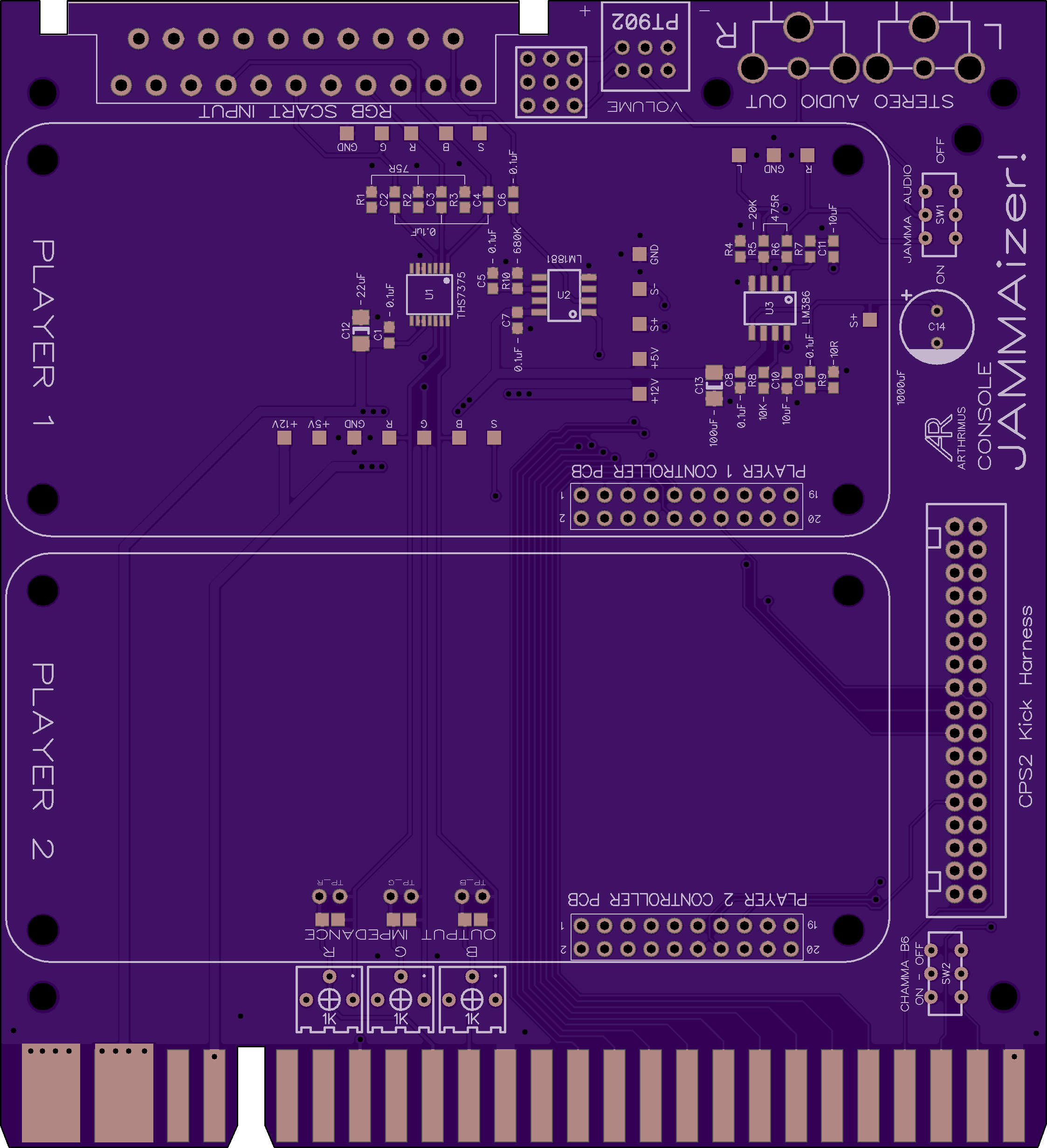
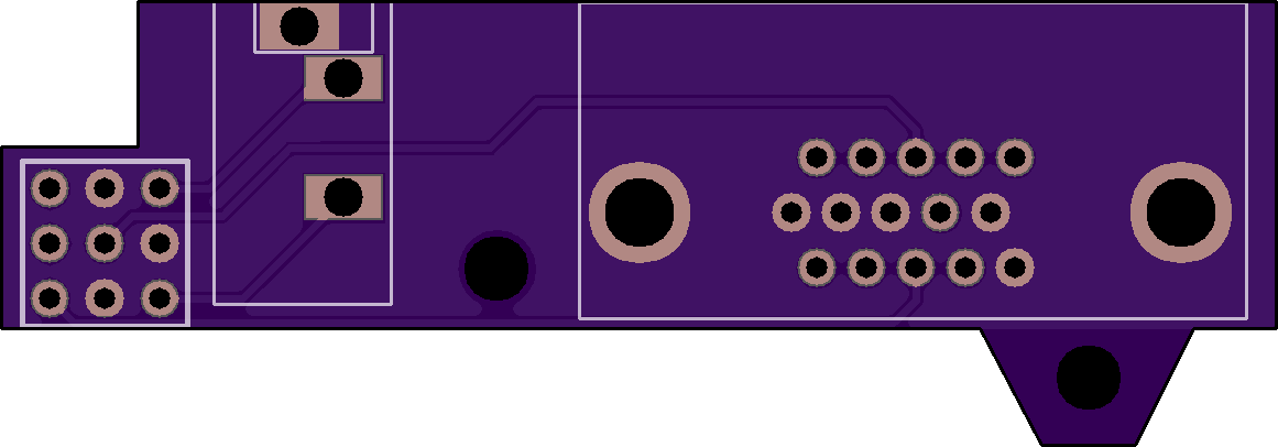
I also did a preliminary layout of the VGA expansion card.
Well that's all for now folks. The PCB house just let me know that my prototypes for the previous revision of the board are complete and should be shipping out tomorrow. I will probably have them by Wednesday so I'll have updates then.
My expectation is that if there is enough interest to do a production run of PCBs I'll probably have lots of extras made, since often the main cost in getting something like this made is just the setup and engineering fees for the board house to do things like hard gold plated fingers and v-groove cuts etc. So if I have a large quantity made I'll still have the option to make changes to the design by producing qsb sub boards that can be soldered to those test points. For example if I change to a different audio amplifier somewhere along the way I could keep using the same base PCB with the new amp board grafted on.
I also did a preliminary layout of the VGA expansion card.
Well that's all for now folks. The PCB house just let me know that my prototypes for the previous revision of the board are complete and should be shipping out tomorrow. I will probably have them by Wednesday so I'll have updates then.
PascalP
Legendary
Wow, pretty cool!!
Gonna follow this for sure
Gonna follow this for sure
waiwainl
Grand Master
Excellent projects you have here!
I'm up for tinkering around with a bare PCB once you go to fab with this.
Test points are a great idea. Opens up this project to allow inputs from a number of different sources beyond retro consoles and PC's (RPi's, retro computers, etc). Test point outputs allow for application in test bench scenarios/non-JAMMA wiring scenarios. Preferably, would like to see test points as 2.50mm spaced headers that are open to air. That would allow for any 2.50mm connectors to be used for quickly disconnecting different sources (JST NH, JST XH, Molex KK series). Afterall, if they are test points; would be nice to quickly disconnect them, rather than permanently soldering them in. Might need to enlarge the vertical footprint a tad to be able to add headers though. But please consider it.
Regarding VGA header, please consider 3.5mm stereo jack input for audio. Makes for easy connection from non-retro console sources. If not, no biggie. Something like this can be used to achieve the same input.
@RGB, would still like to hear further input on the THS-series amps. The docs reference the Sync Tip Clamp as a DC restore circuit. Are we sure these amps don't have DC restoration circuits? The docs do say, DC coupled output can be driven regardless of mode of input. I am not an engineer either.I've tested this circuit with a PS1, SNES, Saturn, and Genesis. I do not experience any brightness fluctuations with the current design, however I did have this problem before I had .1uF capacitors in series with the RGB inputs to the amp. Adding the capacitors allows me to take advantage of the THS7375's Sync Tip Clamp which according to the THS7375 datasheet is described as a DC restoration circuit. I'm not an engineer so I could be misreading this, but it seems to be saying that the STC acts as a DC restoration circuit for AC coupled inputs, and based on my testing this appears to be the case in practice. Please correct me if I am wrong on this.
It does have the DC restoration circuit, but it will only work as intended if the the Sync is embedded within the signal. For this application you'd need to configure the amp in the AC Bias mode and calculate the right bias.@RGB, would still like to hear further input on the THS-series amps. The docs reference the Sync Tip Clamp as a DC restore circuit. Are we sure these amps don't have DC restoration circuits? The docs do say, DC coupled output can be driven regardless of mode of input. I am not an engineer either.
Don't get me wrong - if it works for you, that's all that matters.
Last edited:
Hmm, I was afraid of this. The problem is that I don't know what I should be aiming for as far as the AC bias voltage. I've read that section of the datasheet and understand how to calculate the correct pull-up resistor, but that's only assuming that I know what bias voltage I need. Any help with this would be appreciated if you could spare a few moments of your time.It does have the DC restoration circuit, but it will only work as intended if the the Sync is embedded within the signal. For this application you'd need to configure the amp in the AC Bias mode and calculate the right bias.
Don't get me wrong - if it works for you, that's all that matters.
The thing is, this works on my monitor, but since this will be an open source project that anyone can use and there will possibly be a group buy for PCBs and parts in the future, I want to make sure it works properly on everyone's monitor, and sadly I've exceeded my understanding of analog video signals at this point.
I would like to understand the problem better so if you know of a good source to read up on these concepts I would love to take a look at it. Thanks.
It would be good to test this with other arcade monitors and consoles, it might just do the trick without over-complicating the design.The thing is, this works on my monitor, but since this will be an open source project that anyone can use and there will possibly be a group buy for PCBs and parts in the future, I want to make sure it works properly on everyone's monitor, and sadly I've exceeded my understanding of analog video signals at this point.
Agreed, I'll need to find someone willing to test this who has a large collection of cabinets with different monitors. I don't want this to be a situation where the Toshiba PF monitor that I have happens to be more tolerant of improperly dc referenced signals, and then find out that most other monitors are not so tolerant. In the mean time I have now added the pads for the AC biasing resistors to the PCB layout now, so if it turns out that AC biasing is needed, the option will be on the board already and it will just be a matter of figuring out what value of resistor needs to be installed there.It would be good to test this with other arcade monitors and consoles, it might just do the trick without over-complicating the design.