What's new
Yeah, I was going to try hooking up the digital controls first (shifters, music & view buttons, start, etc); fellow Supermodel emulator author has told me of this as he owns VF3. I'm willing to just cut the pot wires when the board comes and see what I can get, provided I don't fry anything on the controller. I additionally plan to upscale the game to an OSSC for video from the medium-res 15pin VGA to HDMI if that's possible, too.

Worst case scenario, I could probably harvest the entire control panel from a real machine and mount it to a heavy duty surface. :P
 
Loving this thread. Well, I bought a Harley-Davidson LA Riders (Model 3 Step 2) from a trusty arcade shop in China (hasn't shipped yet) that I bought a Scud Race subwoofer from, alongside the original cabinet's wiring harness which I've already got, and wanted to ask general stuff about the possibility of hacking console controls to play it with. It's another driving game but doesn't have additional MPEG audio or force feedback, and my favorite of the Model 3's library next to Daytona 2. I'm pretty new to owning arcade hardware so any advice would be greatly appreciated here!

My goal is to try splicing parts of the harness with a Dreamcast racing wheel -- a Pelican-brand "Rally 2" wheel, which has no pedals but analog triggers with what appears to be 3 potentiometers for brake, gas and steering. The LA Riders game uses 4 but I want to sacrifice the Front Brake for the Rear Brake pedal control. As I've seen other people use the official DC race controller with Scud Race (minus manual transmission), would it be a means of crimping or soldering the appropriate wires from the DC wheel to where the wires are going onto the PCB? Are there extra common grounds involved? This particular game is difficult to find a wiring diagram for because it's one of the less-popular Model 3 titles, but I was wondering what connectors I'd be looking for in the harness to make my inputs from the wheel work on Model 3. I did see useful diagrams on shared on Arcade-Otaku of the M3's wiring and connections, though, like this one:
C23H51o.jpg


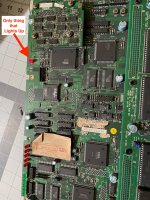
I looked at CN1 on my Harley harness and there's another wire going to pin 9. I wonder if that's the rear brake...

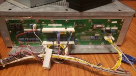
Also attached is a pinout of the wiring that goes to the DC wheel's circuit. Ignore CN6 which is for the vibration motor, and CN1 as that is for the VMU slot. This wheel is additionally very clean, plus easy to open up & understand, so I was wondering if it's possible to wire this wheel to play Model 3 drivers. Thanks in advance! ;)
(There is a little glare on the photo, but the SH I think is for the vibration motor. The wires soldered directly to the circuit are for the steering hence 'X')
This is a great addition. Thank you.
 
OK hopefully my last last question on the CRX-A / B thing.

If I don't have the I/O board for a CRX-A, will the I/O from my CRX-B lineup and connect with the CRX-A with all it's connector points? Or even if it does, will it even work?
 
So, I got my Harley-Davidson Model 3 Step 2 in the mail yesterday from Yaton (it's actually a Virtua Striker 2 Ver.99 conversion), but I've had trouble getting her to boot. I spliced a the AC cable of a Sun Electronics Naomi PSU to a plug from a Dreamcast, and whenever I connect it to my OSSC or my Asus VG245 monitor with the D-Sub connector (I'm surprised this Asus monitor accepted the Model 3 signal on the fly lol), I'll get a faint black screen but with an accepted signal, and it appears the game won't boot. Sometimes I've seen it show an orange screen however. Is one of my boards at fault, or could it be my power supply taking a dump on me?

I threw this Model 3 at another Acer monitor (eventually I'm planning to upscale it to a Gonbes), but that didn't accept the signal at all.

Any advice here is greatly appreciated ;)
 
Have you checked your voltages?

Model 3 is exceptionally power hungry, particularly for 3.3V...
 
Have you checked your voltages?

Model 3 is exceptionally power hungry, particularly for 3.3V...
Actually I got her fixed now. Edit: The actual issue was a loose chip in the board. Pushed it back in & no problems. You never know what the culprit will be with this now 23-year-old hardware, but it works.
Anyone curious, the ROMs burned to the board are a Version 1 of Harley (this one has only the SEGA 1997 copyright on the title screen). :) There was another software revision Sega made in '98 with some checkpoints removed and an updated title screen.
Edit (3/25): Unfortunately, I need to replace the filter board as the one inside currently is incompatible, being a conversion from a non-driving game. I guess Sega intentionally made these filter boards different per game to cut down on costs.
 
Last edited:
So I gave my Model 3 Harley a little play test last weekend after replacing the filter board, and she's running great, except for the SOUND. I attempted to fashion several 4-pin JST NH connectors to either RCA or 3.5mm jacks using the crimp connections, but when I plugged them into CN8 all I got was a ground hum that changes tone every time screen updates. Used a portable Bose speaker I had lying around, and a Lepai LP-168HA amplifier, and both sent out the hum.

I turned the pots of both sound vol and bass shaker vol to max, but nothing. They're not connected to any cabinet amplifiers, but I had noticed my sound ROMs were getting hot, so I quickly shut the Model 3 down. I was actually using a spare 5-pin monitor cable when the chips warmed up, which uses different colors from black/red, but still fits. Additionally I had tested with another PSU with a kit that I bought from France.

A fellow told me he used a black CD-ROM audio cable (for Sound Blaster cards) and soldered female RCA ports to the cable, to power audio from his Virtua Fighter 3, so I feel confident on doing the same as I ordered one and am slowly progressing on soldering stuff.

Got any ideas? Haven't checked my voltages yet but perhaps the best I can do is wait for that cable right now. :)
 
Hello again, hope you're all doing well. I'm back again, only this time with a Sega Model 2A game. After getting my 2B games to work perfectly, I'm having issues with the 2A games I've got, I'm hoping someone might be able to assist here.

It seems like it should be simple enough to feed it 5v power to both inputs at CN3 and CN12 (similar to the Model 2 at CN9 & CN10). And then just feed the Video to CN7 and Audio at CN13. I just wanted to get it up and running so I didn't connect any of the control inputs. When I fired up the board, the only light that lit up solid Red on the board was LED 11. Nothing else lit up.

So am I missing anything else to get a Model 2A game up and running? Or should that be enough? I disconnected video and audio as well just to see if I could get anything else to light up, but no. Curious if LED11 is an error light or if there is something else I need to be connecting to a Model 2A that I'm overlooking.


Thanks in advance for your help.
 

Attachments

  • IMG_6371.jpg
    IMG_6371.jpg
    330.9 KB · Views: 225
Got any ideas? Haven't checked my voltages yet but perhaps the best I can do is wait for that cable right now.

Model 3 outputs line level audio from CN7 and CN8. Some games will have different mixes on different connectors, like FV2 will output music and sound effects from one connector, and just sound effects from the other.

Anyway, take a pic of your current wiring. If your sound roms are getting hot, maybe there's an issue with the motherboard.

It seems like it should be simple enough to feed it 5v power to both inputs at CN3 and CN12 (similar to the Model 2 at CN9 & CN10). And then just feed the Video to CN7 and Audio at CN13.

There's also CN1 for power.
 
There's also CN1 for power.

Oh, I wasn't aware it needed 3 of them. There was no pin header attached to this filter board. OK so I need to buy one of this 10 pin strips and solder it on then.
 
So on this Model 2A I got is 3 boards. Looks like the Rom Game board on top, then two full boards.

My power supply is definitely doing 5v. Model 2B game is working fine, and other games are working fine with 5v.
 
Model 3 outputs line level audio from CN7 and CN8. Some games will have different mixes on different connectors, like FV2 will output music and sound effects from one connector, and just sound effects from the other.

Anyway, take a pic of your current wiring. If your sound roms are getting hot, maybe there's an issue with the motherboard.
Currently I've got the CD-ROM audio cable spliced to female RCA jacks and connected, which works but gives that same hum. That YouTuber who owns VF3 used the same cable and it provided the proper mix like it should.

This is my current wiring setup. I didn't have the analog connectors on, so please forgive me :P. Interestingly, it's a VS2 '99 conversion and did not have a communication board like the dedicated cab's.

Thanks for that reply nem. ;)
 

Attachments

  • 1617401065930741943982743752010.jpg
    1617401065930741943982743752010.jpg
    178.6 KB · Views: 308
Do you have 4 or 3 wires in there?

IMG_6493.jpg
3 for my cable. I'd say the ground is for left and right audio.
I twisted both RCA grounds and had them to one ground. Did the same thing with 3.5mm headphone jacks, and not all wires I used were line-level; they were speaker wires. Wonder if it's my CPU board not talking to me.
When my Harley arrived it had a loose chip that prevented it from booting. Put it through a memory test and all ROMs are good. :)
 
So I could be wrong here but based on the previous info shown here pin 1 is the negative pin for the left speaker.

1617424272651.png


pin 2 does not seem to have a wire coming from it from the positive left line level out.

If you are tying grounds together it would need to be pins 1 and 3 (in your current wiring for the CDrom audio cable you are using, Red and Black)
I am not sure if that would actually cause your speakers to hum per say. You previously had all 4 wires connected with a JST power connector for a floppy drive yes? I would consider going back to that if possible.

Regardless as @nem said this is line level audio so you will be required to use an amplifier. That could be the next target to drill into as your amp could be creating some kind of feed back as well.
The reason I say this is that unless your audio wires are running by something very noisy like a microwave or something lol, you probably wont get feed back introduced through the wires. Though I suppose it is possible.

There's various reasons why you may get feedback on speakers. I have sort of limited experience in troubleshooting such issues yet because I dont encounter it often.
I think I have heard that its possible that if your running an entirely separate ground to your audio amp (like from a different wall outlet) then you could possibly get noise feeding back through ground. How are you powering your amplifier and is the amplifier grounded at all?


Edit: Regarding the Roms becoming warm to the touch. They mostly likely are not involved in the circuit that drives the line level output so that shouldn't be why they get warm to the touch.
I would check the voltages coming from the PSU while the machine is running and if you can the VCC pin voltage on the rom. They should be getting 5V I would think, yes???? If those rom chips for w/e reason are getting more juice than they should then it could cause them to heat up some.
 
So on this Model 2A I got is 3 boards. Looks like the Rom Game board on top, then two full boards.

I was asking how many complete 3-board / full stack motherboards do you have. Previously you mentioned 2A gameS, in plural. If you have multiple stacks not working, more than likely they're not all faulty.

My power supply is definitely doing 5v.

Different boards need different amounts of power. That's why arcade power supplies come with adjustable +5V rails. Model 2 consumes a lot of juice, much more than "regular" game boards. If your 5V is low on the rom board, that could be a reason why the board isn't booting. The fact that your 2B boards are working doesn't really mean anything. You could be starving them off power too. Until you verify, we don't know.
 
So I could be wrong here but based on the previous info shown here pin 1 is the negative pin for the left speaker.

1617424272651.png


pin 2 does not seem to have a wire coming from it from the positive left line level out.

If you are tying grounds together it would need to be pins 1 and 3 (in your current wiring for the CDrom audio cable you are using, Red and Black)
I am not sure if that would actually cause your speakers to hum per say. You previously had all 4 wires connected with a JST power connector for a floppy drive yes? I would consider going back to that if possible.

Regardless as @nem said this is line level audio so you will be required to use an amplifier. That could be the next target to drill into as your amp could be creating some kind of feed back as well.
The reason I say this is that unless your audio wires are running by something very noisy like a microwave or something lol, you probably wont get feed back introduced through the wires. Though I suppose it is possible.

There's various reasons why you may get feedback on speakers. I have sort of limited experience in troubleshooting such issues yet because I dont encounter it often.
I think I have heard that its possible that if your running an entirely separate ground to your audio amp (like from a different wall outlet) then you could possibly get noise feeding back through ground. How are you powering your amplifier and is the amplifier grounded at all?


Edit: Regarding the Roms becoming warm to the touch. They mostly likely are not involved in the circuit that drives the line level output so that shouldn't be why they get warm to the touch.
I would check the voltages coming from the PSU while the machine is running and if you can the VCC pin voltage on the rom. They should be getting 5V I would think, yes???? If those rom chips for w/e reason are getting more juice than they should then it could cause them to heat up some.
The amplifier I tested was indeed grounded, but the hum is not a regular 60hz hum, close to a semitone lower. Same instance on my Bose Soundlink Mini II. The wire I soldered the JST NHs to was anywhere from 26-30 gauges. Crimping or soldering made no difference. That or maybe the sound ROMs aren't properly burned. I scored an untested but clean cage for fairly cheap, however it's the official set so fingers crossed. :)
 
Back
Top