i was refering to reading the ESR valueNot all multimeters will test capacitance, but some will. Mine does.
You are using an out of date browser. It may not display this or other websites correctly.
You should upgrade or use an alternative browser.
You should upgrade or use an alternative browser.
Pincushion Distortion with Sony PVM Monitor
- Thread starter Napoleon IV
- Start date
hatmoose
Enlightened
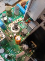
Started work on the transistors today. I have a spare "organ donor" 14M2 that I'm using to sanity check the readings on my parts

Q501
Q503
Q501 I removed, tested, tested again with the multimeter and seems fine, so nothing to see here


Q503 is helfully not in in the service manual of on the diagram, but it clearly there in real life. top work sony engineering QA team!

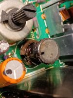
Anyhoo Q503 was a bit more interesting - its a D1133 and there are three classes
class B HFE = 60-120
class C HFE = 100 - 200
class D HFE = 160 - 320
The suspect one showed HFE = 147 and the one from spare parts showed HFE = 86 - not sure if that's the problem but I'll probably swap them around and hope fo the best.


Because if it's NOT that then it will probably be IC509 and changing that is an enormous pain
https://shmups.system11.org/viewtopic.php?f=6&t=65474
I'll also check Q502 just to be on the safe side, but that rarely fails
While I've got it in bits I'll also have a look at the diodes just to make sure - I'm pretty sure that wont be the problem, but it's easy to check now and hard to check later
D506 (horizontal damper)
D502 + D512 (East-west)
Then I'll swap over Q503, put it all back together and hope like hell that I dont have to mess with IC509...
So next steps
Check Q502
Check D506
Check D502 + D512
Q501
Q503
Q501 I removed, tested, tested again with the multimeter and seems fine, so nothing to see here
Q503 is helfully not in in the service manual of on the diagram, but it clearly there in real life. top work sony engineering QA team!
Anyhoo Q503 was a bit more interesting - its a D1133 and there are three classes
class B HFE = 60-120
class C HFE = 100 - 200
class D HFE = 160 - 320
The suspect one showed HFE = 147 and the one from spare parts showed HFE = 86 - not sure if that's the problem but I'll probably swap them around and hope fo the best.
Because if it's NOT that then it will probably be IC509 and changing that is an enormous pain
https://shmups.system11.org/viewtopic.php?f=6&t=65474
I'll also check Q502 just to be on the safe side, but that rarely fails
While I've got it in bits I'll also have a look at the diodes just to make sure - I'm pretty sure that wont be the problem, but it's easy to check now and hard to check later
D506 (horizontal damper)
D502 + D512 (East-west)
Then I'll swap over Q503, put it all back together and hope like hell that I dont have to mess with IC509...
So next steps
Check Q502
Check D506
Check D502 + D512
hatmoose
Enlightened
Not much progress
Q502 = good
D506 = good
D502 + D512 = good
Swapped over Q503, put L509 back in, powered it up and... got exaclty the same problem.
In desperation I will minutely examine the board with a microscope to look for physical damage, and also check C2510 just in case
https://shmups.system11.org/viewtopic.php?f=6&t=69677
But I'm starting to fear that changning IC509 may be in my near future...
Napoleon IV
Student
What's the issue with IC509? Is it especially difficult to change?But I'm starting to fear that changning IC509 may be in my near future...
hatmoose
Enlightened
its a tiny little surface mount SOIC surrounded by other big tall components - I'm going to have to take a dozen parts off the board just to get at it. Luckily the part is easily available and very cheap, so I'll probably just clip legs off the old one rather than trying to hot-air it.What's the issue with IC509? Is it especially difficult to change?
https://nz.mouser.com/ProductDetail/Texas-Instruments/LM358DR?qs=Zu35EjizYSSY6pJ37yjmHA==
It's hugely rare for this to fail (normally Q503 goes) but I've tested literally everything else in the horizontal circuit, this is the only thing left
")
Napoleon IV
Student
Okay, I got as much as I could off and open to get to the A board, and just going off of looks I think it's very safe to say that L509 is the problem. Just look at it! I won't be able to test it until tomorrow at the soonest, but it's clearly all torn up and busted.
Attachments
hatmoose
Enlightened
Dont judge that inductor too harshly based on appearance - they very rarely (never?) fail but they often look like a dogs breakfast.Okay, I got as much as I could off and open to get to the A board, and just going off of looks I think it's very safe to say that L509 is the problem. Just look at it! I won't be able to test it until tomorrow at the soonest, but it's clearly all torn up and busted.
Next step is to carefully remove it, reassemble the PVM, power it back up and see if the horizontal stretch is gone
Napoleon IV
Student
Would it be too rash of an idea to just buy new replacements for all the capacitors listed that could be faulty (L509, Q503, Q501 etc) and replace them all in one go? I can't imagine these cost very much and I'm willing to pay for them if it means eliminating the tedious testing process of opening and closing the TV over and over.
hatmoose
Enlightened
Absolutely! The shotgun approach is my normal one with these old TV's because taking them apart is such a PITA
If you've got one more re-assembly/disassembly in you I strongly suggest you L509 and see what happens while you are waiting for parts tho. That will tell us if it's the transistors or the diodes that are bad
If you've got one more re-assembly/disassembly in you I strongly suggest you L509 and see what happens while you are waiting for parts tho. That will tell us if it's the transistors or the diodes that are bad
Napoleon IV
Student
Ok great! Looking at the manual (and at my TV) I'm having trouble finding out which capacitors are of what type. Where can I go to buy replacements, and how can I tell which is which? And also, how much of this should I expect to replace by applying the shotgun method?
hatmoose
Enlightened
So there are two different things going on here
1) recapping PVM's is highly fasionable
2) our current problem (probably) has nothing to do with bad capiactors so recapping wont fix that
So if you do re-cap this monitor you can expect no improvement whatsoever to the horizontal stretch problem - for that we need to remove L509, trace the problem to either the transistor or the diodes, and replace the faulty component(s)
But if you are absolutely determined to replace those capicators here is my list - these are the same ones on the Savon Pat list.
the first column is the part numbers for www.digikey.com this should go straight into a digikey cart no problems
The second column is the quantities, only need one of each unless you plan to recap multiple monitors
the third column is the spec of the capicator. The mf (capacitance) needs to match, the v(voltage) can be the same or greater
the fourth column is the size (diameter x height x leg spacing) it's important that they ARE this size as otherwise themy may not fit in the space
the fifth column is the description of what cap they are (CXXX) this is critical information otherwise you will have a big bag of parts and no idea what needs to go where
These are really expensive caps, If i was doing this again I would use much cheaper ones for everything except C586, C584 and C572.
Napoleon IV
Student
Ok, I see. So where can i find the transistors and diodes on the board? I assume these are not as easily replaceable?
Edit:
Edit 2: Yes, that does look like these are the same capacitors as Savon's kit, just checked.
Edit:
So you're saying that the capacitors in this list are the capacitors I've already bought from the kit assembled by Savon Pat on Ebay that I posted about a few weeks back?But if you are absolutely determined to replace those capicators here is my list - these are the same ones on the Savon Pat list.
Edit 2: Yes, that does look like these are the same capacitors as Savon's kit, just checked.
Last edited:
Napoleon IV
Student
Alright, good news. I was able to get L509 out through desoldering. I reassembled the unit and tested it out. There's good news and bad news.
Good news is that the image shrunk back down to normal as seen in picture 1, so I know it's Q503 (or hopefully not IC509) that is the problem.
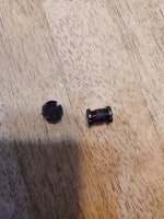
First bad news is that I believe L509 has broken. it snapped when I pulled it out, seen in picture 2. Do you know where I can get a new one (if it is broken?)
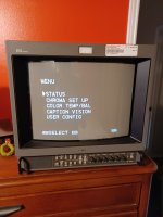
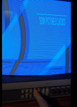
Next is that the TV doesn't seem to be accepting Component input very well. The bottom row of inputs says "RGB/Component," and it works fine with RGB, but when I tried to plug in my DVD player using a Component input, I got picture 3.
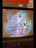
I afterwards tested it out with a Composite video input, and it looked like it was working for the most part. The image was shaking up and down noticeably bad, even with the Menu screen on, but you could tell what the image was at least... (picture 4)
Lastly is a problem I noticed from the start but wasn't as worried about, and it's that audio is completely absent. I got a cable that combines the L and R audio cords into one and tried it in all ports, and I even tried just using the L or R cable without the combiner to see if it would make sound. No luck either way.
So, I think that leaves me with nothing else to ask but where can I buy Q503, since it's not listed on the service manual?
Thanks for all the help btw. Wouldn't be able to do any of this without y'all, It'd have been a waste of money otherwise.
Good news is that the image shrunk back down to normal as seen in picture 1, so I know it's Q503 (or hopefully not IC509) that is the problem.
First bad news is that I believe L509 has broken. it snapped when I pulled it out, seen in picture 2. Do you know where I can get a new one (if it is broken?)
Next is that the TV doesn't seem to be accepting Component input very well. The bottom row of inputs says "RGB/Component," and it works fine with RGB, but when I tried to plug in my DVD player using a Component input, I got picture 3.
I afterwards tested it out with a Composite video input, and it looked like it was working for the most part. The image was shaking up and down noticeably bad, even with the Menu screen on, but you could tell what the image was at least... (picture 4)
Lastly is a problem I noticed from the start but wasn't as worried about, and it's that audio is completely absent. I got a cable that combines the L and R audio cords into one and tried it in all ports, and I even tried just using the L or R cable without the combiner to see if it would make sound. No luck either way.
So, I think that leaves me with nothing else to ask but where can I buy Q503, since it's not listed on the service manual?
Thanks for all the help btw. Wouldn't be able to do any of this without y'all, It'd have been a waste of money otherwise.
Attachments
hatmoose
Enlightened
Wow, lots going on here!
Lets start with Q503 which is a hitachi 2SD1134 like this one https://pdf1.alldatasheet.com/datasheet-pdf/view/62992/HITACHI/2SD1134.html
These are hard to buy from the big component suppliers, but they are all over ebay and aliexpress
this guy claims to have the genuine sony part https://www.ebay.com/itm/384401334353?hash=item59801ae051:g:DV4AAOSwA~phRa0u
or these ones maybe https://www.ebay.com/itm/282404630019?hash=item41c0a0ae03:g:D7MAAOSw32lY0X2n
Before buying new one it would be worth testing the existing one to make sure it actually is faulty. These do actually test out as a proper transistor on a multimeter so it should be reasonably easy to test it (unlike Q501...)
The inductor L509 is going to be harder. I've never actually seen one break before; I thought they were pretty much indestructible.
It's going to need to be replaced - luckily inductors havent changed much in the last 50 years so once you know what you're looking for it should be not-too-awful to source a new one
The sony part number is 1-459-075-11 - what we need is the value.
Normally it would be OK just to read this off the top of the component - but I cant make out the markings on yours. will check mine tomorrow and have a look. In the meantime someone on this forum might know right away https://shmups.system11.org/viewforum.php?f=6
Suggest not worrying too much about the component input or sound just yet, that geometry is the key thing at the moment.
@hatmoose Were there any more installments in this adventure? I've got two 14M4A's that each have different problems, one won't sync on a PAL signal, and misses the first 20% of an NTSC one, the other has this pincushion issue - basically identical. I looked at the board and came to the same conclusion with respect to IC509... I don't have a hot air station atm and the idea of trying to get to the bugger is not appealing in the least.
hatmoose
Enlightened
Hi,@hatmoose Were there any more installments in this adventure? I've got two 14M4A's that each have different problems, one won't sync on a PAL signal, and misses the first 20% of an NTSC one, the other has this pincushion issue - basically identical. I looked at the board and came to the same conclusion with respect to IC509... I don't have a hot air station atm and the idea of trying to get to the bugger is not appealing in the least.
Sadly no more progress on this one - Have successfully replaced IC509 and... absolutely no improvement whatsoever.
I'm not the first person to have been working on this set, so having eliminated every other possible cause I'm now suspecting some kind of damage in the horizontal geometry section. The service manual shows the expected wave forms for all the H-GEO test points, so from here my next action will be to bust out the the oscilloscope.
I've basically put this one on hold for now, too many other cool projects to work on at the moment...
Hi team,
I recently came into possession of a PVM-20M4A which had a blown HOT and blown ICs on the PSU. This monitor had previously been worked on by someone, who really did not do a very good job, including ripped pads, terrible soldering and wrong parts installed. Anyway, I decided to recap the crucial caps in the deflection area while I was in there, most of which are on the sheet above from @hatmoose .
Once I got everything powered up, it produced the exact same deflection issue as above, where the raster was stretched horizontally, and most east-west pincushion adjustments would not make any difference. After spending much time learning how to read electrical diagrams and hours staring at the A board, I managed to fix my issue.
I noticed that in my case, the positive leg of C579 had a lifted pad. Initially, I didn't think too much of this because it was still in continuity with the next part over, R1508. However once I checked the schematics, I realized that this meant that the via wasn't connecting on the other side of the board, and it was directly connected to the Vcc of IC509 .
.
I checked for continuity between the positive leg of C579 and pin 8 of the IC (very difficult as this was underneath the capacitor, used a jumper wire attached to my probes) and confirmed no continuity. So I wrapped a resistor leg around the joint and added a bit more solder to make a good joint, confirmed continuity and when I fired it up, it was fixed!
Here are some pictures
Now from my understanding, this circuit can fail at a few different points, this just happened to be where mine failed. Its best to start at the diodes and work your way from there. I'd start by looking for any short paths to ground across D506, D502, D512 and C525, as well as C514 and C2510. You can do this by checking the resistance across the components using the heatsink of Q501 like this: from the red circle to the four yellow circles, as well as across A and B. You can also do this across the legs of C514 and C2510, resistance should be in the kiloohms or higher (mine was about 53kohms). Also thank you to MKL over at the Shmups forum!
Q503 can also be tested with a multimeter in diode mode once removed from the board. With the red probe on the left leg and the black probe on the middle and then the right leg. You should notice around 0.5-0.7v, with the latter combination being slightly higher. All other combinations should show O/L.
I'd recommend one of the cheap component testers from Aliexpress (like the one @hatmoose has above) if you're looking to desolder and individually test components. They're worth every penny.
I hope you all have some luck in fixing your issues.
I recently came into possession of a PVM-20M4A which had a blown HOT and blown ICs on the PSU. This monitor had previously been worked on by someone, who really did not do a very good job, including ripped pads, terrible soldering and wrong parts installed. Anyway, I decided to recap the crucial caps in the deflection area while I was in there, most of which are on the sheet above from @hatmoose .
Once I got everything powered up, it produced the exact same deflection issue as above, where the raster was stretched horizontally, and most east-west pincushion adjustments would not make any difference. After spending much time learning how to read electrical diagrams and hours staring at the A board, I managed to fix my issue.
I noticed that in my case, the positive leg of C579 had a lifted pad. Initially, I didn't think too much of this because it was still in continuity with the next part over, R1508. However once I checked the schematics, I realized that this meant that the via wasn't connecting on the other side of the board, and it was directly connected to the Vcc of IC509
.I checked for continuity between the positive leg of C579 and pin 8 of the IC (very difficult as this was underneath the capacitor, used a jumper wire attached to my probes) and confirmed no continuity. So I wrapped a resistor leg around the joint and added a bit more solder to make a good joint, confirmed continuity and when I fired it up, it was fixed!
Here are some pictures
Now from my understanding, this circuit can fail at a few different points, this just happened to be where mine failed. Its best to start at the diodes and work your way from there. I'd start by looking for any short paths to ground across D506, D502, D512 and C525, as well as C514 and C2510. You can do this by checking the resistance across the components using the heatsink of Q501 like this: from the red circle to the four yellow circles, as well as across A and B. You can also do this across the legs of C514 and C2510, resistance should be in the kiloohms or higher (mine was about 53kohms). Also thank you to MKL over at the Shmups forum!
Q503 can also be tested with a multimeter in diode mode once removed from the board. With the red probe on the left leg and the black probe on the middle and then the right leg. You should notice around 0.5-0.7v, with the latter combination being slightly higher. All other combinations should show O/L.
I'd recommend one of the cheap component testers from Aliexpress (like the one @hatmoose has above) if you're looking to desolder and individually test components. They're worth every penny.
I hope you all have some luck in fixing your issues.
Last edited:
Hola, acabo de registrarse solo para pasar la información del valor correcto del inductor. He descubierto que es un defecto muy común en los viejos PVM. Te diré lo que he descubierto para que pueda ser útil para ti. En primer lugar, los elementos que se mencionan anteriormente en el hilo generalmente fallan uno o más. El problema es que si uno de ellos está fallando, es necesario cambiarlos todos de nuevo. Te lo digo porque me ha pasado que si cambias uno que falla, el resto ya está dañado. Tienes que poner todo nuevo, no solo en la placa del chasis, sino también en la fuente de alimentación. Compruebe que el voltaje sea de 115 V. Te estoy dando el valor del inductor porque tienes que desmontarlo para comprobarlo. Puede ser herido como lo ha hecho el colega y debería darnos el valor que aparece en la foto. El resto de los elementos deben cambiarse de nuevo.
También los condensadores que funcionan a alto voltaje tienen que ser reemplazados, incluso si el valor es correcto, la resistencia puede no ser correcta y hacer que todo se queme de nuevo.
lm358 es importante que lo cambies cuando lo desmontes, puedes comprobar si estaba funcionando correctamente, pero es muy barato y tienes que poner uno nuevo
Condensadores Str-s3115 m6524 lm358 2,2 años 4,7
Inductor 2sd1878
In the image there is an element circled in red. If the inductor burns, this element may become misaligned. As soon as I can, I will check its value. Checking the resistance is enough.
Perdonar en inglés, pero es el traductor lo que utilizo
Stupid Dufus
Grand Master
Google translation:
Hi, I just registered just to pass the information of the correct value of the inductor. I have found that it is a very common defect in old PVMs. I will tell you what I have found out so that it can be useful for you. First of all, the elements mentioned above in the thread usually fail one or more. The problem is that if one of them is failing, you need to change them all again. I am telling you this because it has happened to me that if you change one that fails, the rest are already damaged. You have to put everything new, not only on the chassis board, but also on the power supply. Check that the voltage is 115V. I am giving you the value of the inductor because you have to disassemble it to check it. It may be hurt as the colleague has done and it should give us the value that appears in the photo. The rest of the elements must be changed again.
Also the capacitors that work at high voltage have to be replaced, even if the value is correct, the resistance may not be correct and cause everything to burn again.
lm358 it is important that you change it when you take it apart, you can check if it was working properly, but it is very cheap and you have to put a new one
Capacitors Str-s3115 m6524 lm358 2.2 years 4.7
Inductor 2sd1878
In the image there is an element circled in red. If the inductor burns, this element may become misaligned. As soon as I can, I will check its value. Checking the resistance is enough.
Sorry in English, but it is the translator that I use