What's new
I don't know anything about restoring CCs, but why not just take the plastic body outside and pressure wash it (on low or just a hose)? Wouldn't that get the stains and smell out a lot better than your ozone thing?
I do own a pressure washer but to get the smoke smell out of something you need a chemical reaction. The ozone reacts with the tar and other chemicals left on the cab to neutralize the odor.

That said a full teardown for a clean down would probably have been the most efficient way to get all the dust/grime off initially. The thing smelled so bad when it arrived and I didn't have time to do a full wash, so I opted for the ozone since setup was quick.
 
For those of you who like cleaning shows:

  • Starting out
PXL_20230922_204951353.jpg

Quick comparison of cleaned vs unclean
PXL_20230922_210312219.jpg

More cleaning action
PXL_20230922_205550383.jpg
PXL_20230924_173107630.jpg

Another cleaning comparison
PXL_20230924_173139072.jpg

Delicious black water
PXL_20230924_175054617.jpg

Exhaust vent on the back before...
PXL_20230924_175936861.jpg

and after.
PXL_20230924_180232280.jpg
 
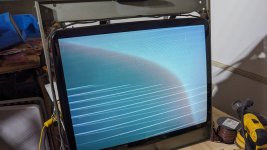
Between sanitizing rounds I decided to mess with the CRT to see if it works.
PXL_20230924_004609667.jpg

The picture above is with no signal. For you veteran arcade enthusiasts can you already see the problem?....


I don't have a PCB to plug into the machine, I thought I would use a raspberry pi I have with a jpac converter. Here's it all laid out:

  • Pi 400
  • microhdmi to vga
  • VGA into JPAC
  • JPAC to the TV
PXL_20230924_004559909.jpg

I set the config file on the pi to a 480p signal and then booted up... to the exact same screen, but aha! I need to twist the knobs:
PXL_20230924_181549525.jpg

-yeah that didnt work. I then tried changing to different hdmi modes on the Pi, which involved pulling the sdcard, editing, putting it back in and restarting. Not a single mode worked.
Since I got fed up trying this, I decided I needed a jamma pcb to at least test with, so I ordered a Pandora's box off amazon to at least confirm the CRT works.
While I waited, I decided to look around the board for something I could spot with a multimeter, didn't take long for me to find that the 2-amp fuse had spotty connection. I ordered a set of fuses (hindsight should have just bought the variety pack) and put in a new one today.

(pic of where I needed to put the new fuse)
PXL_20230924_210040754.jpg


The fuse arrived with the Pandora's box! (new powersupply in picture as well)
PXL_20230926_011809423.jpg

Spoiler - was getting the same image still...PXL_20230924_004609667.jpg
At this point, googling had me believe I needed to get a cap kit and basically spend a long afternoon soldering on the board for the crt. I just happened to catch this page with someone else with a similar problem... and a solution:
https://forums.arcade-museum.com/threads/monitor-diagonal-horizontal-white-lines.383846/

Turned out I had the "screen" dial up to high on the flyback. I turned it down and suddenly colors and graphics were garbled on the screen, a few careful twists of the other knobs and:
PXL_20230926_011802835.jpg


Now, I will admit I spent a good 30 minutes trying to figure out which of the 10 white knobs did the horizontal width and then gave up. I happened to find out about the "horizontal coil" or whatever its called while sitting here typing up this post. Excited to try it out, tomorrow.


P.S. Thank you to everyone for suggestions so far and even some DM's with where to locate parts and such. I really appreciate it.

Next Update - wiring up the cab! PAINTING!
 
Last edited:
Could use some help on the CRT... the horizontal coil looks like this, and it wont move:

PXL_20230926_184657401.jpg


These other pots on the back don't appear to be related to horizontal size. Am I missing something? Also I found this thread and someone identified the chassis as well but didn't provide anymore info. Here's some pics of the CRT board:

PXL_20230926_184648113.jpg

(pic from the other thread - https://www.arcade-projects.com/threads/irico-flat-crt-and-clone-wei-ya-chassis-yatta.26460/ )
Example CRT Board.jpg


Is there a way for me to adjust the horizontal screen size?
 
Is it not the third one from the left that says "H.something"?

Don't do this without confirming but maybe the yoke connector needs to be on the other position? It looks like there's M1 and M2.
 
Is it not the third one from the left that says "H.something"?

Don't do this without confirming but maybe the yoke connector needs to be on the other position? It looks like there's M1 and M2.
H.WIDTJ - this one didn't do anything before, so I tried this again since it seems obvious. It made the screen ever so smaller but not nearly enough. Not sure what to do, the Pandora doesn't have a setting for cutting down the image AFAIK, and its set for jamma display.

Before adjust:
PXL_20230926_202821520.jpg

After adjusting all the way down:
PXL_20230926_202845416.jpg


I do see now the image bows inwards on the sides as well.
PXL_20230926_203007501.jpg

You mentioned the M1 and M2 connections. What does swapping it do? I'm afraid to blow the thing up 😭
[update] did some googling, I believe the M1/M2 is to swap to "mirror image"
 
Last edited:
Pandora's Box isn't a great board to use for dialing in a monitor. I've seen them run at very weird resolutions that cause this exact sort of thing to happen. Do you have access to a different PCB?
 
Pandora's Box isn't a great board to use for dialing in a monitor. I've seen them run at very weird resolutions that cause this exact sort of thing to happen. Do you have access to a different PCB?
Not yet. Working on it.
 
The jumper labeled M1 M2 could either be a 15/24 khz switch or a width mode switch.

I have 2 width modes on my Nanao Ms826 but they are 2 pin on that chassis.

I wasn't able to get full width even on the wider jumper so I had to get a replacement width coil.

If you operate them. I suggest using a plastic CRT adjustment toolset as I burned my hand and possibly shorted it out when I used an allen key.
Swapped the M1/M2. It was a vertical flip mode.
PXL_20230927_214106536.jpg
 
See if there's a resistor inline with the horizontal width pot.

As for the bowing, adjust pincushion to fix that.

pincushion_pot.jpg
 
See if there's a resistor inline with the horizontal width pot.

As for the bowing, adjust pincushion to fix that.

pincushion_pot.jpg
Forgive my ignorance, began learning CRT stuff with this thread creation. I see a resistor on the left of the pot for horizontal width, I would need to pull the board cover and flip it to check correct? If it is inline should I check that the resistor is working or short past it?

1696013358523.png

Pincushion pot doesn't seem to have any visible effect.


And just a general update for everyone:
-all the main painting is complete, I have a few touch up spots that are going to require a store run for 1 more can of paint

Excited to show it to you all and put everything back together.
 
I second the advice to not use the Pandora to test or adjust anything.

It's hard to be patient, but don't start worrying about if your electronics are working correctly until you get a proper board in there. Things might be working a lot better than you think, and there's no reason to worry about resistors etc until you can see.
Fair enough, I keep trying different settings on my Pi 400 trying to get it to work with the JPAC but so far no dice on getting an image. I'm currently shopping for a PCB that won't break the bank.
 
If the pincushion pot isn't working, there's probably something wrong with the chassis. That could also explain why the picture is too wide.
 
Alright, where did we leave off? Painting...

Trigger Warning: the following pictures contain material that may make you uncomfortable. If you do not wish to see subpar prepping, small imperfections, or things you would do better please avoid this post.
At this point I was/am still terrified of breaking anymore of the plastic on this machine so I took an approach of limited risk. I partially dissassembled the unit and only sanded the worst spots to get off gunk or smooth down gouges that I felt I could do safely.


(sanding revealing the hidden inner beauty of this cab)
PXL_20230926_235626190.jpg


I mentioned before that I had found videos claiming this spray paint did not require sanding. I did a test on the front panel to see how it looked.
PXL_20230927_000403852.jpg


Satisfied with this I removed the top/front of the cab, the side rubbers? and then taped up the rest before painting.
PXL_20230928_205910541.jpg
PXL_20230928_223408074.jpg

Tape removed:
PXL_20230929_002731046.jpg
PXL_20230929_002748433.jpg


what about the cat ears?
PXL_20230927_203808739.jpg


Decided to go with a particular color:

PXL_20230927_204054425.jpg


Here's how we are looking: (CPO still on order, about to cancel if I don't get an update)
PXL_20230930_213947426.jpg
 
Getting close or so I thought... it's wiring time:

  • 1st up - the unsafe power plug on the back
    • PXL_20231006_181510179.jpg
    • Added a 3-prong, fused plugin
    • PXL_20231006_183659878.jpg
  • I cut some scrap wood for seating pcb's and the power supply. There's a 3 outlet power strip I added for the monitor and potentially an amplifier.
    • Test and Service buttons are there for now, not sure if they will see much use, so for now, it's just bare microswitches. I thought of potentially putting actual buttons on the wood, but I haven't figured a way to do that and actually be able to remove the wood fom the cabinet. Maybe I should make a tiny box just for those buttons....
  • PXL_20231009_211021391.jpg
Speakers are setup currently as original, no amp at this time. Amazingly the old speakers sound great (you can see I added the marquee back in as well)
PXL_20231009_211142475.jpg


Now I have a noctua fan to install and I also wanted to swap the tube light for an led. However, I've hit a snag.

I briefly ran a 60 in 1 to try out some vertical play in the cab. The monitor rotates by moving the chassis brace over to one side on the mount and then just pulling and rotating the whole thing.

It ran fine but 60 in 1 is single player, so I moved it back and grabbed my single slot neo geo I acquired recently and plugged it all in.

TV: "BZZZZZZTTTT"

Crap, no picture at all.
Checking the board, it appears one of the capacitors is dispensing foam: [Edit - this is just old glue]
PXL_20231009_161925018~2.jpg


At this point. I am definitely bummed out. I'm going to cross-post to the monitor help channel to see what I should do. I'm thinking about ordering one of these universal chassis I see on aliexpress, but I don't know what I don't know.

Hang in there (Ok) Baby!
 
Last edited:
does this chassis require an isolation transformer and are you using one?
 
Back
Top