kebrank
Enthusiast
- Joined
- Sep 1, 2015
- Messages
- 162
- Reaction score
- 102
Great design and price, very cool. I have a question and a couple of suggestions.
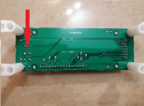
About the LCD, I see a couple of cutouts and the ribbon that connects to the LCD going through them. Is there a reason for this?
Cutouts are cool but one of the points of having the multi enclosed is to avoid the acumulation of dust on the PCB.
I think it would be a good idea to have a + - and a T, for the Volume up, down and Test buttons. Same thing from the LCD panel buttons.
About the fan, given the original one is 60 mm if i’m not making a mistake, the 80 mm Noctua should be perfect for the case.
Thanks,
\o/.k.
")