You are using an out of date browser. It may not display this or other websites correctly.
You should upgrade or use an alternative browser.
You should upgrade or use an alternative browser.
CPS-3 Custom METAL Case
- Thread starter hursit
- Start date
xodaraP
Legendary
@XeD and @cruzlink2 are 2 people I know who have installed these on CPS3 specifically
I have google it already but there are too many options people put in their PCB's.
I really dont understand how people attach it. It doesnt look good to me. When you put your HDMI cable on that small PCB, you can push it easily
But the problem is there is no Hole on the HDMI board to attach it on my Custom Cases.

I really dont understand how people attach it. It doesnt look good to me. When you put your HDMI cable on that small PCB, you can push it easily
But the problem is there is no Hole on the HDMI board to attach it on my Custom Cases.
@cruzlink2 is the man when it comes to these mods. He just did a CPS1 hdmi mod for me in anticipation of the CPS1 multi@XeD and @cruzlink2 are 2 people I know who have installed these on CPS3 specifically

Hopefully they chime in on install/measurements.
I actually just finished this mod today as well as installed it in Hursit's CPS3 case.
Here's the problem:
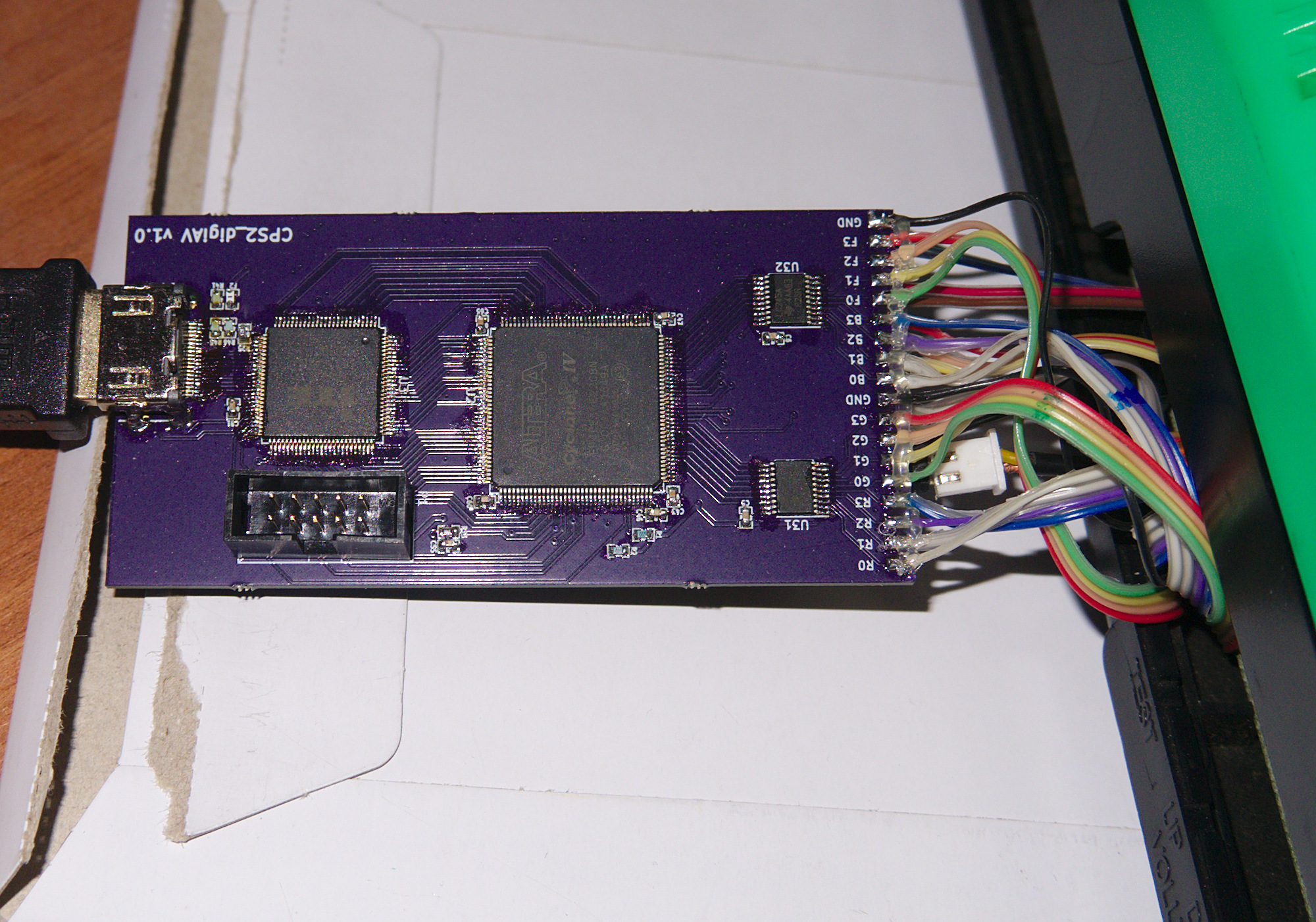
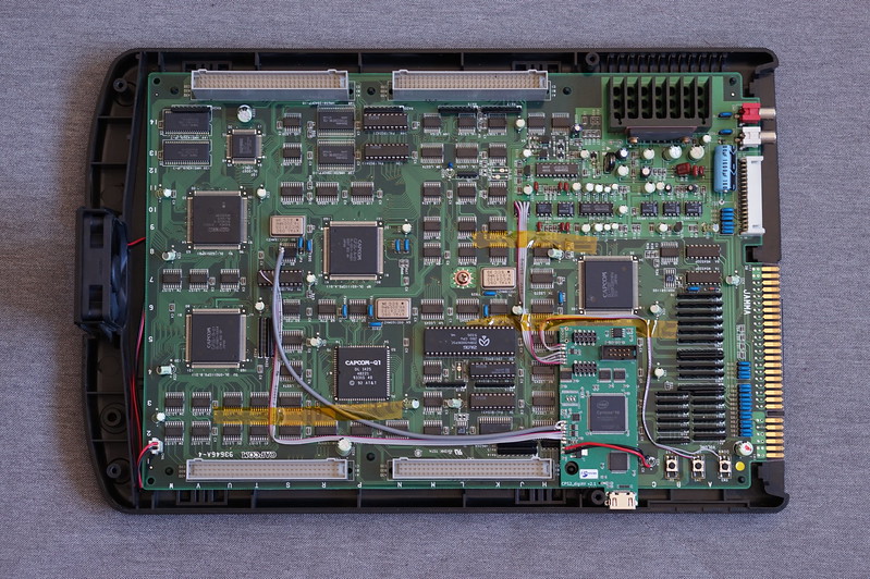
There is no "specific" location the Marqs' digitalAV board installs on the CPS3 board unlike the the CPS2+CPS1 installs where you mount it specifically on certain chips as it solders directly to it. The recommended area to install the digitalAV board on the CPS3 is not exact, as it doesn't mount to anything there, it's literally just held in place with the soldered wires and double side tape.
That makes it difficult to mount the HDMI port exactly at a certain location.
Here's what I did:
I installed it away from the board edge and closer to the middle of the CPS3 board, then I used an HDMI extension and mounted it to the rear. I proceeded to modify the rear the best I could to accommodate the HDMI extender mount.
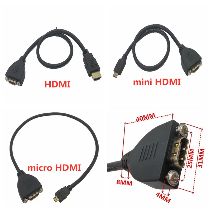
This is the HDMI extension I used: https://www.amazon.com/gp/product/B00M8SLYMK/ref=ppx_yo_dt_b_asin_title_o03_s00?ie=UTF8&psc=1
Refer to Marqs' github for additional pictures: https://github.com/marqs85/cps2_digiav
Hope this helps.
Here's the problem:
There is no "specific" location the Marqs' digitalAV board installs on the CPS3 board unlike the the CPS2+CPS1 installs where you mount it specifically on certain chips as it solders directly to it. The recommended area to install the digitalAV board on the CPS3 is not exact, as it doesn't mount to anything there, it's literally just held in place with the soldered wires and double side tape.
That makes it difficult to mount the HDMI port exactly at a certain location.
Here's what I did:
I installed it away from the board edge and closer to the middle of the CPS3 board, then I used an HDMI extension and mounted it to the rear. I proceeded to modify the rear the best I could to accommodate the HDMI extender mount.
This is the HDMI extension I used: https://www.amazon.com/gp/product/B00M8SLYMK/ref=ppx_yo_dt_b_asin_title_o03_s00?ie=UTF8&psc=1
Refer to Marqs' github for additional pictures: https://github.com/marqs85/cps2_digiav
Hope this helps.
Attachments


Last edited:
Thank you my friend.I actually just finished this mod today as well as installed it in Hursit's CPS3 case.
Here's the problem:
There is no "specific" location the Marqs' digitalAV board installs on the CPS3 board unlike the the CPS2+CPS1 installs where you mount it specifically on certain chips as it solders directly to it. The recommended area to install the digitalAV board on the CPS3 is not exact, as it doesn't mount to anything there, it's literally just held in place with the soldered wires and double side tape.
That makes it difficult to mount the HDMI port exactly at a certain location.
Here's what I did:
I installed it away from the board edge and closer to the middle of the CPS3 board, then I used an HDMI extension and mounted it to the rear. I proceeded to modify the rear the best I can to accommodate the HDMI extender mount.
This is the HDMI extension I used: https://www.amazon.com/gp/product/B00M8SLYMK/ref=ppx_yo_dt_b_asin_title_o03_s00?ie=UTF8&psc=1
Refer to Marqs' github for additional pictures: https://github.com/marqs85/cps2_digiav
Hope this helps.
Is there any technical data for that HDMI Extension cable.
I can put that HDMI and Screw holes on my design easily.
But i really dont know people love it or not

Kavas
Champion
I want one of these for cps2, with HDMI hole. ")
Please can you compare this one with your Extension cable. Maybe it helps.Only info I have is what was available in the Amazon listing. I can try and make measurements of the HDMI extension tomorrow if I can find my micrometer.

I have to check it first.I want one of these for cps2, with HDMI hole.
Cutting the HDMI space on the metal is easy work. .But i have to check it how is it works during the installation.

There are too many different cables on the internet.Did a rough measurement with my ruler, I would say it’s closer to 29mm from center to center.
I have found these cables too. Lets stick on your cables measurements. Peoplecan buy it from amazon easily.

Last edited:
JohnnySlick
Beginner
The name of the project is cps2_digiav, but it can be installed in multiple systems (cps1/2/3). Because it was designed for the cps2, it doesn't necessarily have a specific point on the board to mount to; the actual instructions are "Use mounting tape to attach the board to a suitable place on CPS3 mainboard."
My initial thought would be to just run an hdmi expansion to panel mount cable to the case such that it can be installed close to the signals and still have something sturdy to plug into, but I will do some experimentation and respond to the thread later.
Edit: Whoops, I refreshed and didn't see the next page after your comment. I still need to get some calipers and measure the undamned USB decoders since they actually have mounting holes.
I think it is not necessary another hole on the Metal Case for Undamned USB encoders ?The name of the project is cps2_digiav, but it can be installed in multiple systems (cps1/2/3). Because it was designed for the cps2, it doesn't necessarily have a specific point on the board to mount to; the actual instructions are "Use mounting tape to attach the board to a suitable place on CPS3 mainboard."
My initial thought would be to just run an hdmi expansion to panel mount cable to the case such that it can be installed close to the signals and still have something sturdy to plug into, but I will do some experimentation and respond to the thread later.
Edit: Whoops, I refreshed and didn't see the next page after your comment. I still need to get some calipers and measure the undamned USB decoders since they actually have mounting holes.

JohnnySlick
Beginner

cruzlink2
Grand Master
Yea on the metal case you can just make a hole and use an extension for the output, you do have to be mindful of board placement. For example you cannot do the standard install on a cps2 metal case because it places the hdmi at the edge. In that case you would have to opt for a all wire install of the cps2 digital av to place it somewhere in the center of the A board and have room to plug in the extension hdmi.
I can't for the life of me find my digital calipers. I went ahead and ordered a new pair of calipers on Amazon. It'll be here Wednesday if you can wait, I'll get the measurements for you.@Epyc If you can give me the measurements with digital calipper, i will cut the whole for the new Batch tomorrow.
that sounds perfect. I can wait it of courseI can't for the life of me find my digital calipers. I went ahead and ordered a new pair of calipers on Amazon. It'll be here Wednesday if you can wait, I'll get the measurements for you.@Epyc If you can give me the measurements with digital calipper, i will cut the whole for the new Batch tomorrow.
")
New digital calipers came in. Confirms the rough measurement with ruler previously, 29mm from center hole to center hole. Hope this helps.that sounds perfect. I can wait it of courseI can't for the life of me find my digital calipers. I went ahead and ordered a new pair of calipers on Amazon. It'll be here Wednesday if you can wait, I'll get the measurements for you.@Epyc If you can give me the measurements with digital calipper, i will cut the whole for the new Batch tomorrow.
