MITSU CPS1.5 3/4 Player Helper Adapter w/CPS2 kick

Yeah I figured it out. Thanks. I'm just using the hole on the case instead of rerouting through the jamma edge fingerboard

20230427_152321.jpg
 
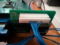
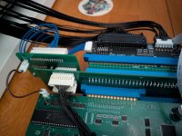
Mitsurugi blue/yellow cables on the first photo seem to have all 10 cables on the connector. But other people photos that I seen have only 8 of the 10 cables. Can someone explain the details of why these extra cables are or not needed?
 
The blue and yellow cables were made by me before I knew that only 8 wires are used for each connector.
 
So last 2 cables are just connected to nothing? Why the boards have a 10 pin instead of a 8 pin?
 
Are these still available? I would need the adapter and the wires too.
 
Hello,
I use an HAS extension harness with my multi CPS1 using the blue CPS3 wire provided with the HAS (which works well with my CPS3).
Unfortunately, I've tried SF2CE, and only punch work, I have nothing on the kick with player 1.
Any idea how to get punch and kick for at least player 1 and 2 with this setup ?
 

Attachments

  • PXL_20260621_170627637.jpg
    PXL_20260621_170627637.jpg
    123.8 KB · Views: 29
  • PXL_20260621_173147192.jpg
    PXL_20260621_173147192.jpg
    201.1 KB · Views: 31
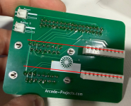
I have an issue with the PCB not lining up properly with the Lions3 cps1 multi case. I believe the issue is because the p3/p4 back white connectors.

This is my own pcb:
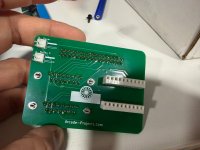
IMG_6322.jpeg

And this is the one Lions3 has on its own multi:
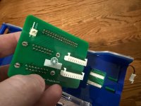
IMG_6390.jpeg

The issue with mine (1st image) is that the white connector holes are too high compared to the version used to design the case (2nd).

My question is: is it just a matter of turning them the other way round (i.e. turn 180º) by desoldering and resoldering, or do I need the other type of connector?

Thanks!
 
Is that picture the outside of the case or the inside? I designed my helper well before he made his case so Im not sure what his design is like.
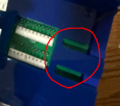
This is the first I've heard of an issue I think.
 
Sorry, I typed my message on the phone too quick and don't think I explained it too clearly.

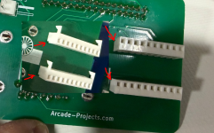
What I mean is that I believe that my board might have the white connectors soldered upside down. If you compare the connectors of the 2 pcbs (mine and Lions3's), their holes are facing up in my pcb unit, while they're facing down in Lions3's own unit, as well as the notches (marked with red arrows) are also the other way round. If that's the case, it's just a matter of unsoldering and resoldering the right way, but since the connectors are slightly different (Lions3's has those "horns" and mine don't) I just wanted to confirm it's not a completely different type of connector before messing anything up!

1784238367581.png

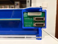
Is that picture the outside of the case or the inside?
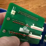
Front outside of the case. The case was designed with the white connector holes lining up with the soldered pins of the joystick connectors in a certain way; since my unit has the white connectors holes offset by a bit (possibly due to the above theory), the PCB doesn't line up well with the case and the joystick ports soldered pins hit the plastic instead of going through the case holes that were made for them (marked red).

1784238473745.png1784239356520.png1784239376143.png

I hope this makes a bit more sense!!
 
To be honest i never soldered those a certain way because I didnt think it mattered. Of course his case is mm precise to the one he must have received. Guess I need to solder them the other way every time just in case from now on.

Yeah you can just desolder, flip, and resolder and it wont hurt anything.
 
Back
Top