nnap
Grand Master
did anybody succeed in converting a rom-1 or rom-4 board to Sengeki Striker?
I should have noted.. the mapping I had in my post is for
ROM4 <-> ROM2
ROM3 isn't mentioned in the mame driver unfortunately. but based on your mapping it seems it's similar to ROM4
there is also a "ROM-BOARD" (with no number, essentially ROM1 I guess) that seems similar to ROM2.
I would think the ROM labels should give you some idea of which position they map to though.
Here's the best picture of a cyvern cart I could find. the ROM labels match the ROM positions in MAME (for ROM2-BOARD) from what I can see.
Cyvern ROM2: https://i.imgur.com/rpUZcBN.jpg
PuzzLoop ROM2: http://www.jammarcade.net/wiki/images/b/b6/Supernova_puzzloop_PCB.jpg
Like a championYou get proper voltages ! And you get proper voltages ! Everyone gets proper voltages !!


Well done sir!You get proper voltages ! And you get proper voltages ! Everyone gets proper voltages !!

Nice one!You get proper voltages ! And you get proper voltages ! Everyone gets proper voltages !!
What would be good cart pcbs to convert to Tel Jan?
I have some spare puzz loops...
I went through my carts and I do indeed have all 4 ROM board variants in my collection.
this is the mapping between the 4 cart variants as best as I can figure

* = educated guess based on position on the ROM board and MAME info.
N/A = not available
Hey, where did you get those nice Mask Rom replacements? Did you do them yourself?You get proper voltages ! And you get proper voltages ! Everyone gets proper voltages !!
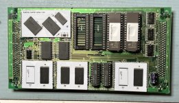
I made the transposer boards myself yes, top board uses a single 24 bit bus transceiver and 3.3V regulator, bottom rows are 5V 8bit roms, so no need for extra logic.Hey, where did you get those nice Mask Rom replacements? Did you do them yourself?
don't use your eyes, use a multi-meter. Test to see if the Pin 44 is tied to ground, or tied to 5V, if neither, test to see if Pin44 of one chip is tied to Pin 44 of the next.I can't see any trace on PIN44 (A20 signal)
Neither connected to GND or +5V, nor chained to other roms' A20 signaldon't use your eyes, use a multi-meter. Test to see if the Pin 44 is tied to ground, or tied to 5V, if neither, test to see if Pin44 of one chip is tied to Pin 44 of the next.
I don't have any other board/cartridge. I supose I'll have to wait until I find another setyou may have to add a wire to chain them together and then identify where A20 should be routed using another board.
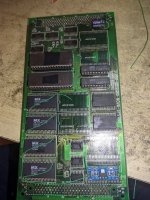
There isn't. The rom sockets you see are the only ones in the photo. That revision of the board hasn't any other below. I suspect nobody has ever made Cyvern/Sengeki Striker with a ROM-BOARD.it may require some logic adjustment too.
the alternative would be to split the ROMs and program as 16Mb but it's not clear if there's enough ROM space for it.
")