Donkey Kong Jr.Nintendo no CLK

I investigated the -5V rail because the large voltage drop was bothering me.


I removed all the ceramic ICs that receive -5V. After removing each component, the supply voltage started to increase gradually. I couldn’t find any logic as to which one might be shorted.


If I remove all the ICs, I measure -5.3V.
If I insert just one IC (any of them, in random order), the voltage immediately drops to -5V and it already draws about 300mA — no matter which IC I insert. As I keep inserting more ICs, the voltage keeps dropping further.


Could my power supply be weak? It draws about 0.3A when all components are installed.
OK, I measured my power supply — it’s bad. It really fooled me.


I need to get a new one.
 
the ECL logic needs minimum 1A in the -5V rail.............
Wow… my power supply could deliver a maximum of 1A on the -5V line when it was new and working properly.
What I don’t understand is this: I had a Mario Bros. PCB before, and it powered that board without any problem.
So why won’t it power this one?
That PCB was basically the same as this one.
 
* The -5V is usually used for the audio and RAM sections. Potential faults include capacitors, operational amplifiers, and RAM modules.
On this PCB -5V is also used in the clock circuit:

1771189265215.png


It's used to create an AC signal that will go through the coil.
 
I repaired the power supply. The PCB draws 300 mA on the -5V line. The screen is still black. On CPU pin 6 (CLK) I measure a low signal.


So which crystal oscillator is supposed to provide the clock signal to the CPU?
 
Thank you for the schematic. The clock signal is present on pin 13 of the 10136, but at the Q1–Q2 outputs I only measure about -1V.


Does this mean the IC is dead? Unfortunately, I don’t have a spare 10136 to replace it.
 
Last edited:
How do you measure the outputs of the 10136? They are pulsing signals, you'd need an oscilloscope to observe them (or a logic probe powered between -5V and +5V).
What about the !Ø34 signal?
 
How do you measure the outputs of the 10136? They are pulsing signals, you'd need an oscilloscope to observe them (or a logic probe powered between -5V and +5V).
What about the !Ø34 signal?
Unfortunately, I don’t know exactly where point 34 is located.


Does point 34 correspond to pin 2 of the LS163?
 
How do you measure the outputs of the 10136? They are pulsing signals, you'd need an oscilloscope to observe them (or a logic probe powered between -5V and +5V).
What about the !Ø34 signal?
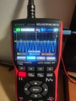
10136 pin13.....This oscilloscope can only measure up to 50 MHz.
 

Attachments

  • 17712769762167061431260244340436.jpg
    17712769762167061431260244340436.jpg
    148.9 KB · Views: 14
Back
Top