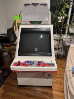
Hitachi GMK-29FSN possible horizontal collapse?

Donutman

Student
Joined
Apr 6, 2024
Messages
41
Reaction score
19
Location
NC
Hey everyone. I recently acquired a Neo Candy 29 cabinet with that has a Hitachi GMK-29FSN monitor. I bought it knowing that monitor had issues. However, to start trouble shooting I set it up, plugged it into a step down transformer 120V>100V, and powered it up. An image briefly showed up but then collapsed to the single vertical line in the middle, and then nothing.

I quickly turned it off, but could see that the electron gun was no longer firing. The rest of the cabinet works fine, sound, marquee light, etc. so to me this seems to be a HOT issue? If anyone has any insights I'd appreciate them before I start tinkering with everything.

Also if anyone has a service manual or knows where to find one I would really appreciate it. My googling has yielded nothing.


IMG_5045.jpeg
 

Attachments

  • IMG_5044.jpeg
    IMG_5044.jpeg
    208.4 KB · Views: 29
horizontal collapse are rare.
it would be this line:

[ | ]

but I suspect you have vertical collapse:

[--]

Can you confirm?

and now you seem to have multiple issues.

#1: no power:
have you checked fuses?
Can we see pictures of this chassis ?
with the power unplugged: can you check the HOT with a multimeter in diode mode? black in the middle, red on both side: should read between 0.4 and 0.6

#2: vertical collapse:
fix #1 first! but you might need to change the VERTICAL IC (picture will help)
 
Thanks for the response!

What I saw definitely looked like [ | ] when the image collapsed.

I can't pull the chasis out at the moment but I took as many pictures as I could with it in the cab.

From what I can tell it looks like the fuses are okay?

Also if there is a way to figure out the HOT without a schematic it would help me. I'm kinda poking around blindly at the moment.

IMG_5054.jpeg
IMG_5055.jpeg
IMG_5057.jpeg
IMG_5058.jpeg
IMG_5060.jpeg
IMG_5061.jpeg

IMG_5062.jpeg
IMG_5063.jpeg
IMG_5064.jpeg
IMG_5067.jpeg
 
from neo geo forums

The flyback its an HITACHI 2435048, impossible to found one on the market but the good news is that usually they are so strong. When you have no picture you just look at power section where is the HOT FN651 just replace this transistor and these caps: C740. C915, c924, c906, c902 then magically the chassis will work perfect again. MOst important you must use a stepdown transformer for japan application 100v (120 or 110 not are good for these chassis)
I have performed this on 3 dead chassis and now they work perfect.

find this HOT FN651?
 
Alright I'll look for it once I can pull the chassis and actually see the print on the transistors
 
Alright. Some progress... For starters I have determined the a Hitachi GMK-29FSN is not remotely the same as a GMK-29FS2. I order the parts based on the referenced post, and once they arrived I pulled the chassis and lo and behold they don't match up at all.

Now this is my fault for not checking, but honestly info on these Hitachi GMK monitors is scarce so I just rolled with it. Anyways, with the chassis now out I started to go through everything and try and identify the specific issue. One thing that is obvious is that this monitor has been recapped and they seem to all be correctly oriented and the soldering job was decent enough so I don't suspect the caps at the moment.

I started trying to identify the HOT and think I found it
IMG_5151.jpeg


I took my multimeter and tested it and I think it is shorted. Before I order a new one can any confirm that I tested this right (first pic is red on B -> C, second pic is red on B -> E)? Just want to double check before I order any more parts.

IMG_5157.jpeg
IMG_5158.jpeg
 
usually it's black on top and red on each side.
looks like your first measure is good ...

Yeah that is what I thought but on the PCB it looks to be clearly labeled B-left C-middle, and E-right. It is kinda throwing me off because I used to the CBE configuration.

For what it is worth when I measure I put black on the middle and red on the left and right I get the same .482 reading.

I guess I'm just double checking because the PCB seems to be labeled differently than what I would expect to be the case.

Also found this datasheet for the part the confirms the BCE configuration.
 
Last edited:
Alright I think I solved the transistor issue and I think it is just a nonstandard leg layout, thus the HOT is fried.

I found another BCE configured transistor on the board that I don't suspect has issues.
IMG_5172.jpeg


I then used the multi meter to measure from B > C and then B > E and I got .784 at both readings
IMG_5166.jpeg
IMG_5168.jpeg


I went back to the suspected HOT and the B > E reading still gives .000 and beeps. At this point I'm pretty sure it is the HOT like initially suspected, just to much evidence at this point for me to think otherwise. I really wish there was more documentation on this chassis variant it would certainly make this easier and give me a tad more confidence.
 
Yeah, very few info on those GMK chassis, I have a GMK-29FJ in my Pony IV, again quite different from 29FSN or 29FS2, not sure why they felt the need to have so many different chassis for the same tube size.
Anyway, from your tests it seems your HOT is blown, now it may be a consequence of something else failing upstream or downstream. Before replacing it I'd check the components around (capacitors, diodes, resistors, etc.).
 
Yeah, very few info on those GMK chassis, I have a GMK-29FJ in my Pony IV, again quite different from 29FSN or 29FS2, not sure why they felt the need to have so many different chassis for the same tube size.
Anyway, from your tests it seems your HOT is blown, now it may be a consequence of something else failing upstream or downstream. Before replacing it I'd check the components around (capacitors, diodes, resistors, etc.).
Thanks for the advice. I'll check those components as well. It is gonna take a few days for a new HOT to arrive so I have some time to verify the other components in the area.
 
You need to remove the HOT and test it out of circuit. It's very common for HOTs to read as shorted in circuit on newer (as in, newer than a K7000) chassis.
Alright I did that and when the HOT is out of circuit B > C reads .62 and B > E reads .656... so guess that means that HOT is fine?

I'm curious does the false negative reading in circuit mean anything. Like does it help me to tract down when could be the issue? I ask because I tested resistors and diodes in the area. I visually looked at the film capacitors and I can't find any smoking guns yet. Just hoping I can narrow my search in some way.
 
Alright so I ordered new HOT and @trashedcabs you were right I get a false negative on both HOTs in circuit and they both check fine out of circuit. So I don't think this is the issue at this point. I started going over the components on the board again and I found an odd capacitor in the power section that seems to be oriented incorrectly.

The suspicious capacitor is C764 and it looks like it wasn't installed with the negative and positive in the correct spot. The last two pictures show the underside of the board where C764 is and then C764 in relation to Q705 (the HOT).

Again it is hard to know exactly because I don't have a schematic, but wanted to see what folks think before I start pulling off random components.

IMG_5185.jpeg
IMG_5184.jpeg

IMG_5186.jpeg
 
The suspicious capacitor is C764 and it looks like it wasn't installed with the negative and positive in the correct spot. The last two pictures show the underside of the board where C764 is and then C764 in relation to Q705 (the HOT).
C764 is fine, it's just that the negative side is soldered to an alternative point, maybe because the other one is already taken by the yellow wire. Could be from factory.
 
Alright new information. I kept using the multimeter and testing parts but everything checked out fine. So I threw the chassis back together and got it back in the cab... still no video no electron gun.

However, in all my searching I came across a thread that mentioned plugging the monitor directing into a step-down transformer, instead of the plug on the PSU. So going for the Hail Mary I plugged the monitor into the step down directly and it worked... or at least I can see the electron gun glowing, I hear it power on, and when I power it down I see the characteristic white static/collapse.

Now the weird part is when I power on the rest of the cabinet I still get no video. So the new question is

Why would the monitor work when plugged in directly to the step down, but not when the cabinet is powered on? Probably a PSU issue, but honestly this is one of the weirder things I have ever encountered. Any insights, tips, tricks, whatever would be appreciated.

Also I'm also just plugging in an empty PGM board for testing and can hear the intro music and the SFX of the service menus, but no picture shows.
 
It could be going into protection due to high B+. It's not uncommon for monitors that were adjusted for 100v input voltage to need their B+ turned down when they run off 120v. I've never had a Hitachi chassis before so I couldn't tell you where the pot is to adjust it or what voltage it should be set to. Usually you can measure the B+ rail voltage off one of the output diodes after the power supply if there's no marked test point.
 
So even though I’m feeding it 100V through a step-down converter, turning 120V to 100V, it is going into protection?

Sorry for the silly question, just trying to make sure I understand.
 
From what I understand, when you power the monitor directly from the wall or inside the cabinet, the monitor refuses to power on. When you run the monitor outside the cabinet through a step-down, it powers on. Is that correct, or am I missing something?
 
Back
Top