In this thread we build the projects that others have shared - PicoRom is a DIP32 ROM/EPROM emulator that you can program on the fly with a USB cable

hatmoose

Enlightened
Joined
Mar 25, 2021
Messages
1,420
Reaction score
3,026
Location
New Zealand
PicoRom is a DIP32 form-factor ROM emulator - up to 2Mbit in size and 70ns access speed
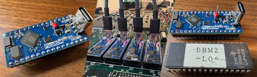
use_collage.jpg

Github page here
https://github.com/wickerwaka/PicoROM

and cool writeup here
https://hackaday.com/2024/11/05/picorom-a-dip-32-8-bit-rom-emulator/

PicoRom does a bunch of cool tricks, but the coolest one (for me) is being able to connect via USB and push arbitrary data to it on the fly. My main use case for this is goofing off with NeoGeo carts but lots of other arcade hardware uses the Dip32 for various weird and wonderful EPROMS that are becoming hard to get or inconvenient to program.

You can buy one of these, tested, working and fully assembled for $28 which (as we will see in a moment) is an insanely good deal. So if you just want one that works, buy from here https://www.tindie.com/products/pbretro/picorom/

But - if you're like me and have to everything the hard way, then you're in the right place
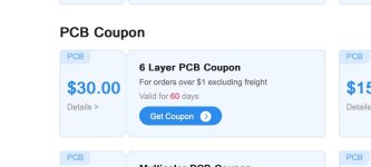
 
Version 1.7 (the most recent) is a 6 layer board - normally these are hilariously expensive to produce but JLCPCB currently have a promo for $30 off 6-layer boards so I applied that.
JLC.jpg

Unfortunately these boards are not particularly cost effective for PCB assembly - they are dual sided, and have many components that are "basic" rather than "standard". And several of the components were out of stock when I ran the job. So plan B is hand soldering and hot air.
 
This is the cart that I ordered for parts - given that the whole thing needs to fit into a DIP32 package there are a lot of exceptionally tiny parts in here.
https://www.digikey.co.nz/short/55wfn8h8

SMD 0201 is roughly .5mm x .3mm
even placing these by hand requires a good microscope and expensive tweezers. To solder them its either a proper micro-iron or hot air.

It was about this time that I realised I had forgotten to order the stencil when I placed the order for the boards...
 
Let me know how the build goes! The design is optimized for size over everything else so it uses a lot of small and sometimes hard to find components. I have never tried to assemble one myself and I'm pretty confident I would fail if I tried. I switched to a 6-layer PCB after struggling to route a few final signals on the 4-layer version. The cost increase is pretty minor when you are getting 50 or 100 made at once (I've used that argument a lot of times to justify other BOM cost increases!)
 
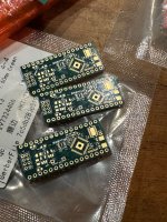
Boards arrived today. I’ve never worked with 6-layer before, the quality is magnificent, it’s like jewellery.
IMG_0148.jpeg
I changed the USB header to 2mm IDC for these boards for my use case.

Will start work on fabrication shortly
 
Let me know how the build goes! The design is optimized for size over everything else so it uses a lot of small and sometimes hard to find components. I have never tried to assemble one myself and I'm pretty confident I would fail if I tried. I switched to a 6-layer PCB after struggling to route a few final signals on the 4-layer version. The cost increase is pretty minor when you are getting 50 or 100 made at once (I've used that argument a lot of times to justify other BOM cost increases!)
Thank you for your amazing work on this project and for your words of encouragement with the build - loving that you have shared your work - It is amazing to learn from and understand and a great inspiration. What you do is noticed and appreciated!
 
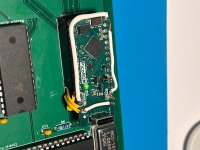
Hopefully not too much of a thread resurrection, but just to express my thanks to @wickerwaka for the picorom project. Despite my misgivings, I assembled them myself - decent solder paste, the correct stencil, stereo microscope and precision heat gun made it a rather enjoyable task. I had originally hoped that at least one of the 5 would work - but so far have 4 working examples. I adapted the design marginally to fit a different USB connector as I couldn't get the one specified. All other parts were readily available through either Mouser or Digikey.

It does exactly what I hoped it would do - removed the need for constant removal of the EEPROM from my 65C02 project to flash it. Adding it to the makefile in VS code complete automates the process. A picture below ( the additional wiring is to adapt the 32 pins to the 28 pin EEPROM that I am using, although I note that there is a 28 pin version now on the repo.
 

Attachments

  • IMG_6705.jpeg
    IMG_6705.jpeg
    176.7 KB · Views: 44
Back
Top