Konami Windy II - good to great - a refurb

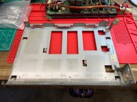
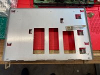
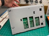
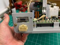
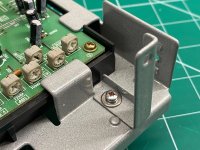
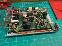
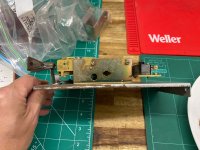
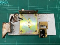
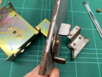
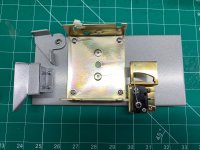
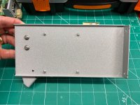
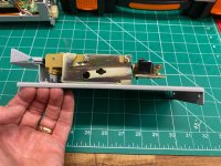
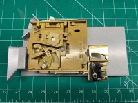
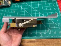
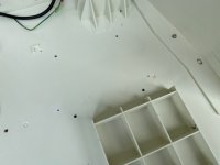
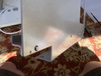
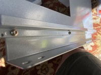
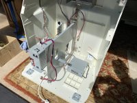
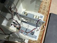
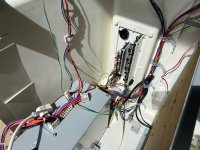
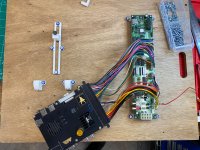
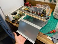
I went all-in on making the chassis tray nice. It’s a different setup to the Tosh 7534 so I’m gonna have to do some mods to make it fit nicely in the machine.

BEFORE
IMG_5296.jpeg
IMG_5297.jpeg
AFTER
IMG_5785.jpegIMG_5891.jpegIMG_5892.jpegIMG_5893.jpeg
 
Last edited:
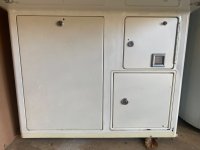
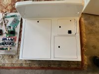
Although I’m not going to be painting the cabinet, I did get the metal doors at the front and rear access panel powder coated in a colour called pearl white. It was the closest match I could get to the white pearlescent finish of the cabinet and you’ll see that it is a bit of a warmer tone which is a little unfortunate, but when looking at the front under the control panel, I don’t think it will be too bad.

BEFORE
IMG_4518.jpeg

AFTER
IMG_4888.jpegIMG_5802.jpeg
 
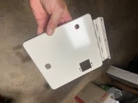
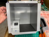
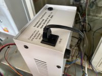
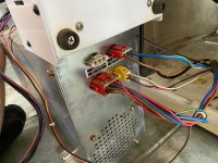
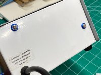
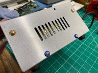
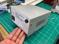
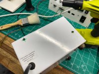
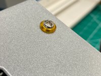
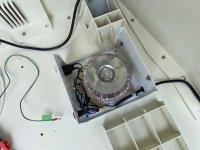
The stepdown converter in this thing was originally bolted to the top of the power supply. Basically a bit of a hack job, although it was somewhat thoughtful because they didn’t drill any new holes in the power supply, just inside the stepdown converter. It also had a groove cut out of the back of the top so it would sit flat on the power supply when screwed down. I cleaned it up as best I could with the Dremel and then had the top powder coated in the same silver finish as other parts in the machine. I patched out the holes that they used to mount it, just with some screws to look more tidy. It’s ready now to bolt into the floor of the cab in a better place. Some before and after pictures:
IMG_7370.jpegIMG_7371.jpegIMG_5765.jpegIMG_5763.jpegIMG_5762.jpegIMG_5752.jpegIMG_5764.jpeg
 
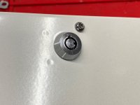
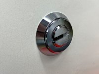
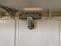
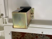
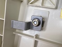
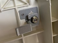
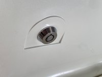
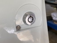
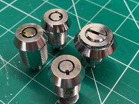
Here are all the locks etc. fitted to the front and control panel areas. The part that the front access panel tang secures against is the only part I missed in the disassembly and did not powder coat. I blanked out a few of the holes that were near locks with some torx screws. Sadly, when fitting some of the locks the big threaded nut that holds them on does dig into the powder coat when tightening it. I might try and source some large specialised washes to protect the powder coat in future. I also scratched a couple of the freshly plated tangs with a spanner, but you live and learn. One of the locks on the bottom of the control panel also needs a bit more polishing by the looks of it up close.

IMG_5906.jpegIMG_5907.jpegIMG_5911.jpegIMG_5913.jpegIMG_5915.jpegIMG_5919.jpegIMG_5918.jpegIMG_5917.jpegIMG_5916.jpegIMG_5904.jpeg
 
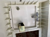
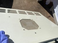
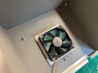
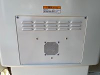
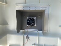
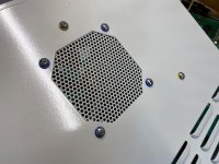
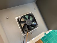
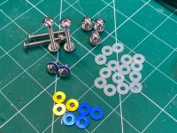
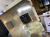
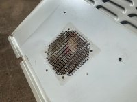
The Windy II revision 2.0 has a fan inside a shroud fitted to the back of the cab access door - to cool the neck board I assume. I painted the shroud as it was corroding and cleaned the fan and fitted it all with either polished or brand-new hardware. I added a few nylon washers on the inside to protect the paint. I was gonna put nylon washers on the inside of the anodised washers however I just nipped up the screws carefully and it shouldn’t dig into the powder coat that way. It came up quite nicely, I think. I haven’t added any quieter Noctua’s at this stage but will consider it later on. Although not in the power supply. That ship has sailed. I’m not going back in there. 🤕 Some before, and after shots again – hopefully you can tell the difference. Also, I was of the impression that this fan blew air onto the neck board - however it pushes air out of the vent and doesn’t suck it in. Has anyone else experienced the reverse?
IMG_4531.jpegIMG_4532.jpegIMG_5996.jpegIMG_6002.jpegIMG_5998.jpegIMG_5995.jpegIMG_5997.jpegIMG_5993.jpegIMG_2963.jpeg
 
Last edited:
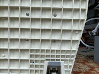
I had to drill four holes in the bottom of the cab to fit the stepdown converter – not my favourite thing to do, but it’s better than having the power supply piggybacking the step down converter and looking horrible. There were already four tiny holes here, and a little raised plastic corner guide for something similar. I’m guessing in another market somewhere perhaps? The bottom of the cabinet still looks a bit dirty, but it’s not really dirty and just has rub marks from where it’s been dragged across concrete or whatever and is impossible to clean to a white finish.
IMG_5989.jpeg

IMG_5986.jpegIMG_5988.jpegIMG_5987.jpeg
 
Last edited:
And here’s where I’m up to today 16.1.26. I applied new double sided adhesive tape to all the cable retainers that I cleaned thoroughly, and placed them in the cabinet where they were originally. There were two metal bendy ones that I didn’t replace and instead are using new clips. I expect I’ll probably add a few more to really get the cable routing nice and neat.
IMG_5990.jpeg
IMG_5999.jpeg
 
Last edited:
Today I got the power supply mounted and connected a bunch of cables to it. As expected I chose to add more adhesive cable retainers. I’m inexperienced at setting this up with the JAMMA adaptor so need to do some research and reading to make sure it’s done properly. Some cables go from the power supply to the JAMMA adaptor while others I think go to the IO. I’m also missing some cables, but I believe they’re for original Konami hardware which I don’t have. So I think I can get away without them - although I could build new cables if I can find the right JST parts online. It’s the last 10% of these machines where it can get tricky - as far as trying to retain the original parts and work out what’s been cut out/off over the years. I also got the PCB wooden board holder mounted. Most of the spot welds on the channel the wood slides along had broken, so I drilled some holes and put some little JIS M3 nuts and screws in there.
IMG_6016.jpeg

IMG_6013.jpegIMG_6014.jpegIMG_6015.jpegIMG_6017.jpegIMG_6018.jpeg
 
In order to work out the cable routing, I need to put in a game board and Jamma adaptor. I’m going to use my Mistercade as it will give me the best bang for buck and variety in this cab in yoko orientation. I’m also keen to make the most of the good stereo sound in the cab and have a direct video connection to the chassis. I had to put the Jamma adaptor 180° to what was in the manual so the Jamma edges would line up properly but I don’t think it really matters. I used one of @NFGx board holders for the Mistercade and it’s sitting nicely.
IMG_6024.jpeg
IMG_6019.jpegIMG_6022.jpegIMG_6023.jpeg
 
Last edited:
Everything here is connected for setting up the cabling. The Mistercade remote, the audio out and the video out. I’ve made it such that you can pull the board out the whole way only after releasing a couple of clips in the base. To make sure I don’t pull it out without remembering to undo the clips I’ve used the original wing screw that holds the board in place. Quite a few other wires and the USB(JVS) cable will have to be fed up through the control panel when that’s fitted.
IMG_6025.jpeg
 
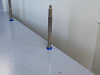
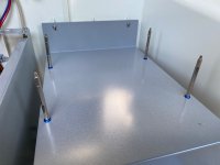
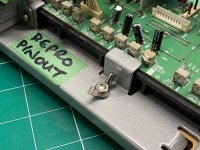
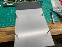
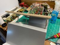
After quite a bit of thinking I’ve come up with a plan to mount the 2930 chassis in a way that does justice to the resto. The wires from the neck board to the chassis are short and the chassis has to be mounted up high like it is when it sits in the original frame of the 2930 monitor. Using the original chassis mounting holes I’m going to mount a plywood board on four standoffs. I’ll then sit the chassis on this board which will sit snugly between the overhanging edges of the chassis frame - and secure it with a screw and nut using more stand-off bits. I’ll just have to drill one hole in the chassis frame. It will make sense when I post the finished pics. To get to this point I had to loosely connect the original chassis mounting shelf to the top of the coin box receptacle and also the PCB board holder. I say loosely because the coin box receptacle is screwed directly to the front lower portion of the cabinet frame, so you have to do incremental adjustments to sort of bring it all together at the end. If you tighten them all up first and then put the bottom front cabinet portion on, the holes to the coin box receptacle won’t lineup.
IMG_6026.jpeg
IMG_6028.jpegIMG_6027.jpeg
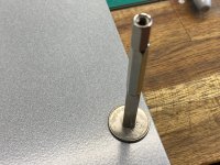
Note. I ended up mounting these stand-offs the other way round by screwing them into the shelf and then putting a nut on the bottom.
 
Last edited:
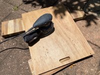
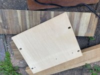
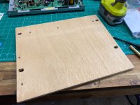
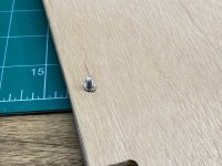
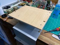
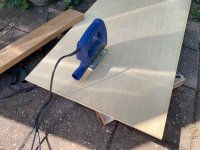
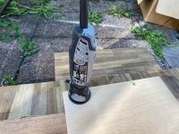
Okay, I bought some AA marine ply and cut it to size and gave it a sand. I then drilled and routed out spaces for the 45° tabs that protrude from the bottom of the chassis. This was fiddly because my Dremel bits aren’t that sharp and I don’t own set of files. I also drilled three holes where the screws that secure the chassis to the chassis frame also protrude through the bottom. Lastly I drilled a hole a bit smaller than a 12mm stand-off and then tapped the stand-off into the hole and put a screw in the bottom of the stand-off. Unfortunately when I tapped it through the wood it pushed up a layer of ply 😤. I should have tapped it through from the top.
IMG_6032.jpegIMG_6033.jpegIMG_6034.jpegIMG_6035.jpegIMG_6036.jpeg
 
Last edited:
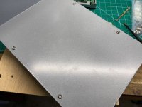
Next I assembled the support stand-offs. I had to join a number of them together, but if anyone knows where to get really long ones let me know. I fastened them to the original holes of the chassis shelf and used some ¥50 coins partly for a laugh but really for practicality to support the metal around the thread. I then screwed the wooden shelf down onto the supports making sure to countersink the wood to allow the screws heads to sit below the surface.
IMG_6041.jpegIMG_6042.jpegIMG_6043.jpegIMG_6044.jpegIMG_6045.jpegIMG_6046.jpeg
 
Last edited:
Back
Top