
You are using an out of date browser. It may not display this or other websites correctly.
You should upgrade or use an alternative browser.
You should upgrade or use an alternative browser.
M92 Multi front spacer
- Thread starter plasticfactory
- Start date


The M92 Multi (everyone should have one!) uses a spacer + PCB foot to act as a standoff stack on the front of the board. This solution is ~1.4mm taller than the rear board stack-up, causing an equivalent amount of flex on the top board.
While I work on a proper enclosure for this, I did a (very) quick model of a printable spacer to remove the flex. The hole offsets were measured with a digital comparator, so location should be very accurate.
The part was designed for M3 heat set inserts, but you could also use a longer bolt + nut.
I included STEP files so that adjustments can be made in the event that other people are using different length standoffs, or any other number of variations that could exist. I think the model as-is will cover most people.
If anyone who needs one does not have access to a 3D printer, post here -- I can probably help.
printables link
Right:

Left:


Here you can see the difference in height + flex (slightly exaggerated as my board had some flex already) when only swapping one bracket:

Do you have any plan to sell it ? I would be interested

plasticfactory
Champion
I've made them for free -- if you need a set just PM me your address.
plasticfactory
Champion
Surprised at how many people PMd me about this. I'm printing a pile now and will send them out to everyone who messaged me.
I'd also like to plug Semload's case -- his stuff is always really high quality and if its as nice as my M72 case, would recommend it to anyone with an M92 multi.
I'd also like to plug Semload's case -- his stuff is always really high quality and if its as nice as my M72 case, would recommend it to anyone with an M92 multi.
Last edited:
Surprised at how many people PMd me about this. I'm printing a pile now and will send them out to everyone who messaged me.
I'd also like to plug Semload's case -- his stuff is always really high quality and if its as nice as my M72 case, would recommend it to anyone with an M92 multi.
I don’t have any semload case yet for my multis, I have to consider
RepairGuy95
Champion
Get em while he is making batches.
They're nice. He has a system 16 too.
They're nice. He has a system 16 too.

Semload
Professional
@Semload is this part compatible
with your case?
ATTENTION: this support is not compatible with my Case that I created. I have already created an alternative with normal metal spacers. You can see it on the sales post in the PCB instructions. In the case there will be suitable spacers.
(In the photo the L-shaped feet are black, the ones I attach to the case will be white)
See the attached photo:
Attachments
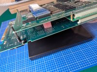
ATTENTION: this support is not compatible with my Case that I created. I have already created an alternative with normal metal spacers. You can see it on the sales post in the PCB instructions. In the case there will be suitable spacers.
(In the photo the L-shaped feet are black, the ones I attach to the case will be white)
See the attached photo:
The pcb looks bent a little bit
Semload
Professional
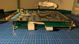
This is a photo of the spacers being installed. The PCB is temporarily resting on a box. This is not its final position.The pcb looks bent a little bit
THE PHOTO IS ONLY FOR SHOWING THE SPACERS.
New photo attached:
As you can see, the PCB does not flex in any way.
Attachments
Last edited:
plasticfactory
Champion
I finished these up for everyone who PMd me. I should ahve them shipped out tomorrow.
plasticfactory
Champion
You did!

9999 Damage
Grand Master
Unfortunately, your spacer design didn't work for me. My MT2 ROM board is too short to reach a standoff from that hole in the mainboard:ATTENTION: this support is not compatible with my Case that I created. I have already created an alternative with normal metal spacers. You can see it on the sales post in the PCB instructions. In the case there will be suitable spacers.
(In the photo the L-shaped feet are black, the ones I attach to the case will be white)
See the attached photo:
I figure I can continue using Plasticfactory's spacer to keep the motherboard and ROM board from compressing together, but I don't have a good way to keep them from splaying apart (since there's no motherboard standoff hole corresponding to the end of the ROM board where I would attach the plasticfactory spacer). Maybe storing it on its side will be sufficient.
For the acrylic case connection, I'll have to extend a PCB foot and standoffs from the motherboard to the case without the ROM board in between. (Future tense because I ran into issues with my M92 board that I'm still working through.)
Last edited:
plasticfactory
Champion
Sorry for the delay, I finally shipped these out to everyone who PMd me. International users, please be patient as they were sent FedEx International Economy.
As for the Semload case -- I used my spacers. The measurements for these boards simply do not line up to get exact spacing with off the shelf parts. I did have to swap included kit hardware with taller standoffs (I can't remember the exact height) but everything ultimately fit nicely.
Word to the wise: be careful with your Semload M92 enclosure. There is a lot of gloss acrylic on that case. When I rub my hand across the surface I get an audible POP from so much static buildup. This isn't a knock on his product, I am very happy with mine.
As for the Semload case -- I used my spacers. The measurements for these boards simply do not line up to get exact spacing with off the shelf parts. I did have to swap included kit hardware with taller standoffs (I can't remember the exact height) but everything ultimately fit nicely.
Word to the wise: be careful with your Semload M92 enclosure. There is a lot of gloss acrylic on that case. When I rub my hand across the surface I get an audible POP from so much static buildup. This isn't a knock on his product, I am very happy with mine.
Nice! Do you have a picture of how you used your spacers? Would be keen to put mine back inSorry for the delay, I finally shipped these out to everyone who PMd me. International users, please be patient as they were sent FedEx International Economy.
As for the Semload case -- I used my spacers. The measurements for these boards simply do not line up to get exact spacing with off the shelf parts. I did have to swap included kit hardware with taller standoffs (I can't remember the exact height) but everything ultimately fit nicely.
Word to the wise: be careful with your Semload M92 enclosure. There is a lot of gloss acrylic on that case. When I rub my hand across the surface I get an audible POP from so much static buildup. This isn't a knock on his product, I am very happy with mine.

plasticfactory
Champion
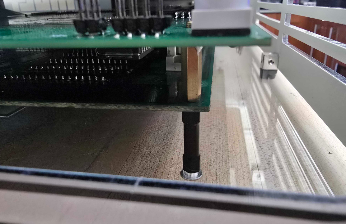
I'm pretty sure all I had to do was swap the bottom acrylic>board standoffs with 15mm, and otherwise install like normal. Be sure not to tighten anything to the bottom until all the screws are in. This allows you enough wiggle room with the PCB location to ensure the left spacer fits without touching the acrylic. A better solution would be to revise the standoff design, but hey, this works.
I failed to take a picture of the entire front opening, but the height difference is negligible in terms of the JAMMA edge being raised toward the top of the enclosure.
If you try this and it doesn't quite add up please let me know and I'll see if there was anything else.
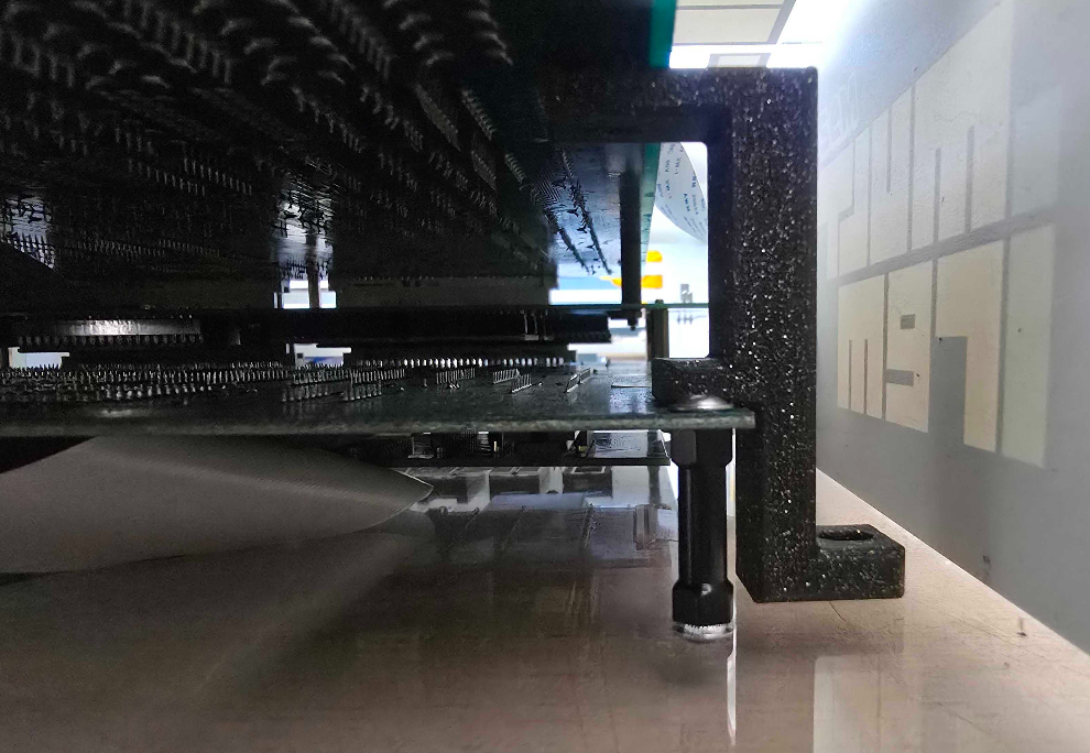
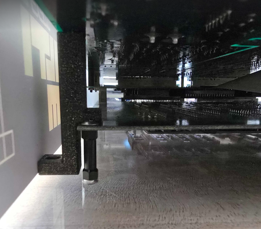
I failed to take a picture of the entire front opening, but the height difference is negligible in terms of the JAMMA edge being raised toward the top of the enclosure.
If you try this and it doesn't quite add up please let me know and I'll see if there was anything else.
Last edited: