M92 no power

9999 Damage

Grand Master
Joined
Mar 18, 2022
Messages
832
Reaction score
1,282
Location
San Francisco, USA
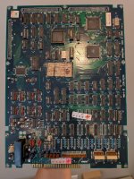
I had a working M92 Multi with a recapped motherboard and a MT2 ROM board. I started installing it into the new Semload case. I ran the board a couple times during install to make sure I wasn't entombing it with badly seated ZIF connectors or something. At some point, it just stopped working. The HAS supergun LCD and my PSU voltmeter remain off, which makes me think there's a short somewhere tripping the PSU's protection.

Some naughty things I may have done while trying to install the case:
  • Smushed motherboard components so a leg might be bad touching another leg
  • Flexed the motherboard, which could have broken a solder joint or worse
  • M92 Multi ZIF cable may have been off by one

Some variables I've tried:
✅ Different PCB - other PCBs work with the same setup
❌ Different PSU - no change
❌ Different supergun - no change
❌ Remove ROM board & multi - no change (suggesting the issue is on the motherboard itself)

Some tests I've tried:
❌ Continuity between GND & +5V: None found (tested at JAMMA edge)
❌ Continuity between GND & -5V: None found (tested at JAMMA edge)
❌ Continuity between GND & +12V: None found (tested at JAMMA edge)

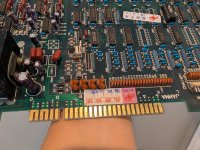
The diodes at D1 & D2 are protection diodes, right? They have uneven black stripes, but they didn't look obviously burnt to me.
 

Attachments

  • PXL_20260721_203834789.jpg
    PXL_20260721_203834789.jpg
    338.6 KB · Views: 31
  • PXL_20260721_203840494.jpg
    PXL_20260721_203840494.jpg
    297.2 KB · Views: 21
Something I neglected to mention in the initial writeup: since the issue first occurred, I've had 2-3 instances where the supergun powered up and everything worked (except for corrupted background graphics in NBBM, maybe due to a badly seated ZIF ribbon). But then on a subsequent power cycle, I'm back to no evidence of power from the PSU and supergun alike.

measure your 5V pin at or near the JAMMA edge to see what you get for output

DC test shows a 5.00V difference between GND and +5V when the supergun and PSU voltmeter are showing power, 0.2 mV when they're not (but the PSU is switched on). Is that expected?

what is the resistance between 5V and ground on the PCB when the JAMMA edge is disconnected
540Ω is good, right?

I straightened all the through-hole components I smushed when the board was upside-down for the case install, just in case a component leg was shorting. While I was at it, I noticed the resistor array at RA17 is broken. Anyone know what it governs?

M92 RA17.jpg
 
that RA17 is definitely broken and needs to be replaced. probably worth solving that before troubleshooting further

ZIF ribbon
I'm not sure what a "ZIF ribbon" is.
ZIF stands for "Zero Insertion Force" and is the name of the sockets with a lever like what you find on a chip programmer or the CPU socket on a motherboard
they're called zero insertion force because none of the pins make any contact when you insert the chip, and then the force is applied after insertion using the lever.

M92 like most PCBs don't have any ZIF sockets or connectors on them what-so-ever
 
Resistor array: It’s labeled 8-103JAHDK. I can’t find anything about the specs with a search, so I’ll measure the resistances tonight and try to find a matching part.

ZIF: The M92 Multi’s flex ribbon cables connect to zero insertion force connectors on the multi board and ROM board. I mention them because it’s possible that I seated one of these off-by-one and sent voltage where it doesn’t belong.
 
Resistor array: It’s labeled 8-103JAHDK. I can’t find anything about the specs with a search, so I’ll measure the resistances tonight and try to find a matching part.

ZIF: The M92 Multi’s flex ribbon cables connect to zero insertion force connectors on the multi board and ROM board. I mention them because it’s possible that I seated one of these off-by-one and sent voltage where it doesn’t belong.
你是中国人吗 我知道这个排阻的替代型号
 
你是中国人吗 我知道这个排阻的替代型号
Thanks. The resistor array appears to be a 10 kOhm 8-resistor 9-pin bussed array, so I bought a Bourns 4609X-101-103LF.

I installed it yesterday, but must have done something wrong since I’m getting O.L between pin 1 & 2. Might be a bad solder joint on pin 1 because of the big ground plane. I’ll take another look today.
 
Thanks. The resistor array appears to be a 10 kOhm 8-resistor 9-pin bussed array, so I bought a Bourns 4609X-101-103LF.

I installed it yesterday, but must have done something wrong since I’m getting O.L between pin 1 & 2. Might be a bad solder joint on pin 1 because of the big ground plane. I’ll take another look today.
This is the model
 
Took an extra day to complete the RA17 install since apparently SW3 switches 1 & 8 tie RA17 pins 2 & 9 (respectively) to ground. So, now RA17 is replaced and all pins are testing at 10 kOhm resistance to pin 1.

But the original symptom persists. I've been over the board a couple more times looking for shorts, but I haven't found anything. The supergun still occasionally powers up, but then not on the next power cycle, so maybe there's intermittent contact due to a cold solder joint. I'll keep looking, but I'll also be grateful for any other ideas of what to check.
 
Last edited:
The real savior in those situations is a milliohm-metre to identify the point of least resistance. It's quite a cheap device.

Also, it's possible it's unrelated to your case install, maybe just a bad coincidence.
For instance those TTL chips with bold markings from TI are known to short when they fail:

1785467591809.jpeg
 
Also, it's possible it's unrelated to your case install, maybe just a bad coincidence.
For instance those TTL chips with bold markings from TI are known to short when they fail:
Good clue. Do you know off the top of your head what I should check, or do I need to look up the datasheet to figure out which continuities are expected vs. not? I took a look earlier today and realized I would have to learn more EE basics just to understand the diagram.
 
They simply become shorted between Vcc and ground.
Got back from travel, looked up pinouts, and tested all the LS244, LS245, LS139, LS20, etc. I could find. None had continuity between GND and VCC, but every GND pin connected to JAMMA GND and every VCC pin connected to JAMMA +5V. So, that looks okay.

I can't find any evidence of a short between GND and +5V (or the other JAMMA power pins). Maybe my assumption that there's a short is wrong, though I'm not sure what else would cause the aforementioned symptoms. Since the supergun sometimes powers on for one run, then doesn't power on in subsequent runs, there must be something driving the inconsistency, e.g.:
  • Overheating
  • Charged capacitor drives different behavior than discharged capacitors
  • Cold solder joints making intermittent contact (either factory solder or from when I recapped the board)

I'm grateful for all the ideas so far, and eager for any others people might have.
 
It doesn't make much sense to me as the Vcc pins of the TTL chips are directly connected to the JAMMA +5V, therefore if it's shorted at the JAMMA edge you should find the same short on any chip connected to 5V, unless there's a main power trace completely severed.
 
It doesn't make much sense to me as the Vcc pins of the TTL chips are directly connected to the JAMMA +5V, therefore if it's shorted at the JAMMA edge you should find the same short on any chip connected to 5V, unless there's a main power trace completely severed.
I don't see continuity between GND and 5V at the JAMMA edge. Sorry if that was unclear. I wrote some notes to this effect in the OP.

I only speculated that there's a short based on the PSU/supergun behavior (sometimes acts like there's no power at all), but I can't find any evidence of a short. I'm inexperienced in diagnosis and repairs and don't know what else could cause these symptoms.
 
No worries.
Can you take a pic of your setup when everything is plugged (PSU/Supergun/PCB)?
 
Back
Top