Hi all, first time poster here. Also first arcade machine I've ever worked on, so still learning a lot.
TLDR: TM-202g monitor has green tint, transistor swap didn't fix, power resistors on neckboard are stupid hot.
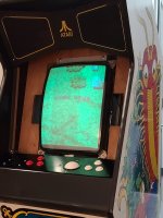
I'm in the middle of repairing/modifying a Millipede upright cab, and was hoping for some electrical help regarding the monitor. It's a Matsuhita 19" TM-202G, which seems to be original for this cab. I've completely recapped it, but when powering on the monitor has a strong green tint to everything (see attached pic). I tried adjusting the R and B Drive pots (no green one present), along with the brightness and RGB Low Light pots, but can't seem to get the colors quite right no matter how much I tweaked it. Clarity and geometry seem plenty fine, just colors are off. I didn't get to mess with it for very long, as you'll see shortly. Also, FYI I did set the B+ voltage to spec (123V) according to the service manual, if that helps at all.
So based on some googling, I tried replacing the three RGB drive transistors on the neck board, as I read that they can cause color issues if they go bad. No change at all, so I swapped them back to the old ones. Used NTE157 transistors as replacements. My multimeter doesn't have a transistor tester built in, and I was struggling to test them with voltages/resistance, but since there wasn't any change I don't think they are the issue (could be wrong though).
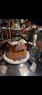
Then I noticed some smoke rising from the neckboard, and that the R351-R353 Power Resistors were burning hot to the touch. So hot that they were melting the solder their legs were mounted with. I assume that isn't normal at all. The resistors still measure 4.7k ohms as rated, so I think they're okay. So my current assumption is that some other component that feeds them is bad? I didn't notice it before I tried replacing the resistors, but it's very possible that it was doing the same beforehand (and they still smoke with the old transistors put back in).
I ain't an electrical engineer and still learning how to read circuit diagrams, but it seems that these power resistors maybe get 180V from the main board? Then the signal meets with the transistors, goes through R354-R536 and into the tube? So would I check the voltage from the main board next, and I can do that with a basic digital multimeter? Or does anyone have any experience with similar issues, and know where I should try troubleshooting next?
Service manual here for reference (I think the schematic for the neckboard is page 25): https://www.arcade-museum.com/manuals-monitors/Atari Monitor TM-202 1st Printing Matsushita 19in.pdf
Appreciate any help or advice y'all can provide!
TLDR: TM-202g monitor has green tint, transistor swap didn't fix, power resistors on neckboard are stupid hot.
I'm in the middle of repairing/modifying a Millipede upright cab, and was hoping for some electrical help regarding the monitor. It's a Matsuhita 19" TM-202G, which seems to be original for this cab. I've completely recapped it, but when powering on the monitor has a strong green tint to everything (see attached pic). I tried adjusting the R and B Drive pots (no green one present), along with the brightness and RGB Low Light pots, but can't seem to get the colors quite right no matter how much I tweaked it. Clarity and geometry seem plenty fine, just colors are off. I didn't get to mess with it for very long, as you'll see shortly. Also, FYI I did set the B+ voltage to spec (123V) according to the service manual, if that helps at all.
So based on some googling, I tried replacing the three RGB drive transistors on the neck board, as I read that they can cause color issues if they go bad. No change at all, so I swapped them back to the old ones. Used NTE157 transistors as replacements. My multimeter doesn't have a transistor tester built in, and I was struggling to test them with voltages/resistance, but since there wasn't any change I don't think they are the issue (could be wrong though).
Then I noticed some smoke rising from the neckboard, and that the R351-R353 Power Resistors were burning hot to the touch. So hot that they were melting the solder their legs were mounted with. I assume that isn't normal at all. The resistors still measure 4.7k ohms as rated, so I think they're okay. So my current assumption is that some other component that feeds them is bad? I didn't notice it before I tried replacing the resistors, but it's very possible that it was doing the same beforehand (and they still smoke with the old transistors put back in).
I ain't an electrical engineer and still learning how to read circuit diagrams, but it seems that these power resistors maybe get 180V from the main board? Then the signal meets with the transistors, goes through R354-R536 and into the tube? So would I check the voltage from the main board next, and I can do that with a basic digital multimeter? Or does anyone have any experience with similar issues, and know where I should try troubleshooting next?
Service manual here for reference (I think the schematic for the neckboard is page 25): https://www.arcade-museum.com/manuals-monitors/Atari Monitor TM-202 1st Printing Matsushita 19in.pdf
Appreciate any help or advice y'all can provide!
Attachments
Last edited: