

dillingerradio
Professional
Hey everyone!
This post will contain details surrounding cap mapping and recapping a SUN model 400-5397-01 PSU, as well as the conversion of a U.S. standard power cord to provide power to it, and the creation of a custom cord to provide power to a HAS v5 supergun unit from the remaining PSU plug.
Recap Summary:
This information was previously posted in the Sun PSU cap map thread; however, in the interest of keeping that thread clean and on topic, I've moved the bulk of the 'story' over to its own thread here, and reformatted it so it's easier to read.
The SUN 400-5397-01 is- from everything I've read and seen- the gold standard PSU for the NAOMI. Moreover, it becomes critical equipment for NetDIMM operations, since JAMMA supplied power is insufficient. While other models (and ATX conversions) exist, the 400-5397-01 just works. Subsequently, I opted to pick one up for my NAOMI system since I wanted to eventually put together a NetDIMM multi. A good price for this PSU is about $50-$75, and I saved a search on eBay until I managed to find one in good looking condition that was described as having tested functional, which I bought for just shy of $68. I also ordered a recap kit for the 400-5397-01 from Arcade Parts and Repair.
When the PSU arrived, I tested its functionality and found it to be satisfactory; however, I had already intended to recap it, so I removed the cover and had a look at the interior. My decision wound up being a good choice, as a number of the electrolytic caps had indeed failed. This is where my inexperience at the time comes into play, and I made a silly mistake that cost me a lot of time and effort: Before verifying the cap kit I bought actually matched my hardware, I went through and desoldered all the caps on the unit, without documenting them, only noticing the mistake when the caps I went to replace them with weren't the same.
At that point, I began furiously looking through the forum. It was then I stumbled upon the SUN PSU Cap Map thread. I was unpleasantly surprised to learn that- not only did this PSU have several internal hardware revisions- I just happened to have a revision which hadn't been previously documented. So, not only had I foolishly purchased the wrong cap kit, but I also had only a limited knowledge of where the original caps actually went. At that point in my experience level, I was not meticulously documenting what I removed.
So, I decided to review all the information I did have to try and figure it out. Thankfully it went pretty well, actually:
The only ones I struggled with were the 4 x 1000uF 10V (colored black) and 1 x 1000uF 16V (colored blue) which occupy spots: C25, 26, 27, 28, and 32.
Initially, I didn't think I had any photos that would resolve the matter, which left me in the uncomfortable position of having to guess where the 16V went. However, after reviewing the available imagery again, I noticed I had one photo that just barely shows spot C27. In my perception, that small sliver of the cap in the light is decidedly blue (meaning the 16V). I asked a few others, and they also thought it appeared blue. That was enough to convince me that the 16V actually goes in C27, and the 4 x 10V subsequently occupy slots C25, 26, 28, and 32.
You can decide for yourself by having a look at the original photo and the two caps which I was struggling to differentiate (the top is a 10V and the bottom is the 16V):
The rest of the 1000uF 10V caps had clean tops. But the one that did happen to go? It went virtually identically to its cousin, as you can see- crazy coincidence, and also crazy annoying (because if they'd all been clean, or at least different, then there would be no question). In any event, it wound up being irrelevant. At that point I had managed to resolve the rest of the cap map, and I opted to simply bump the troublemakers all up to 16V to avoid the issue entirely.
Cap Map:
Conversion of U.S. Standard Wall Plug:
The 400-5397-01 is rated for AC input from 100-120V, 3A, at 50 or 60Hz. Standard wall outlet power in the U.S. falls within that range, and so- in my particular case- that means my unit can be converted to use a wall plug.
As far as getting power to the unit, at first I thought I might convert the box to a standard 3-prong panel mount and Dremel out a spot for it (which would make it more portable and cables pretty easy to find.) But, after some consideration and discussion, I determined to keep the original connector, so that it could be put back into a cab at will. Subsequently, I decided instead to modify a wall plug to use the PSU's native connector. A brief search on Amazon yielded a perfect cable with inline switch for this, from generic brand Filshu. I bought a couple to modify.
As for connectors, the PSU utilizes Amp Up connectors, with parts numbers as follows:
The cable side uses the TE CONN RCPT HSG 3POS 3.96MM receptacle, with the TE CONN TAB 16-20AWG CRIMP TIN male pins.
The PSU side utilizes the TE CONN PLUG HSG 3POS 3.9MM plug, with the TE CONN SOCKET 16-20AWG CRIMP TIN square female pins.
With the connectors and cord in hand, I went ahead and configured it for use with the power supply by pinning the connector with the wires matching the orientation of the connector coming from the PSU. The PSU does not have a ground wire, so instead I crimped on a fork to allow it to slot under a screw on the exterior of the PSU case. Once that was done, I put together a fresh connector for the PSU-side as well, since the old one was looking a little sad. I likewise refreshed the wires going to the fan control unit. Strictly speaking, this wasn't necessary, I just opted to since I was already in there.
With the power cord sorted, the PSU recapped, and everything in order, the job was done. It's been a while since I completed these modifications, and I've used the PSU now several times since then, and it's been rock solid. At the moment, I use it to power a NAOMI 2 NetDIMM WiPi NetBooter multi setup, along with HAS v5 supergun. While 2 of the unit's plugs connect to the NAOMI, a custom power cord I made draws 5V from the remaining plug to supply the HAS v5.
Power to HAS v5 Supergun Plug:
[ EDIT / UPDATE ]
This plug is not necessary. I only made it so I could have a "self-contained" setup, which didn't require any additional power sources (e.g. running the SUN to the NAOMI and a Meanwell to the HAS.) If you don't want to make one, you can simply use whatever power supply you regularly use with your HAS unit.
With that out of the way, one of the things I discovered when working with a few different I/O's is that I failed to take into account the power requirements of the I/O. Specifically, the audio amplification circuit, which may need 12V (e.g. in the case of TD-IO). For that reason, I later remade the cable with both 5V and 12V rails, and I would recommend you bear in mind the power considerations of your specific I/O setup when making your own solution.
[ END EDIT / UPDATE ]
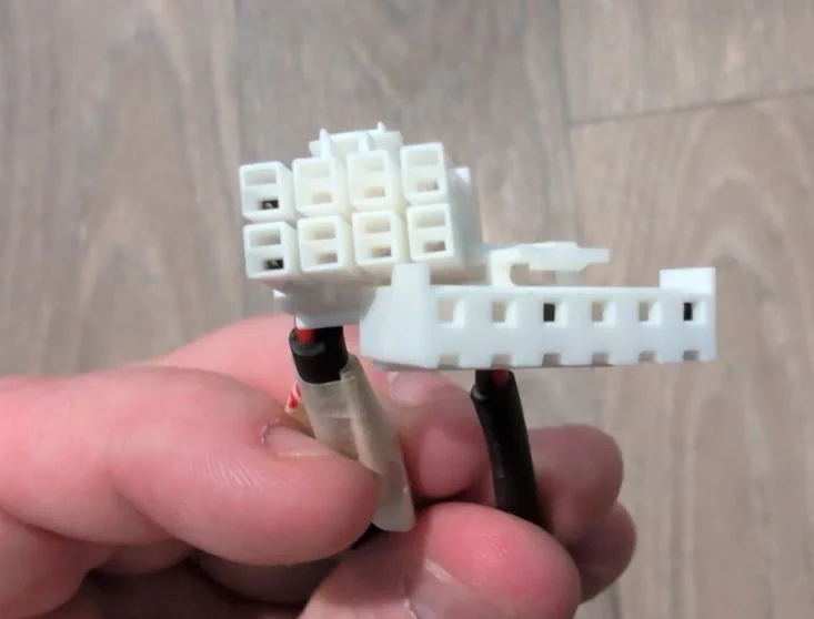
This cord is intended to use the remaining power plug on the PSU to provide 5V to the HAS v5 supergun (which is what I have). The plug has both 5V and 12V rails (along with ground,) but the HAS unit only needs +5V and ground, so the cord will just be a simple 2-wire. Additionally, it will need a couple connectors, one for interfacing with the PSU and one to interface with the HAS.
Subsequently, I picked up the following:
With everything in hand, it was time to get them pinned up. Thankfully, SUN has made it blissfully easy, and provided voltage mappings on the PSU:
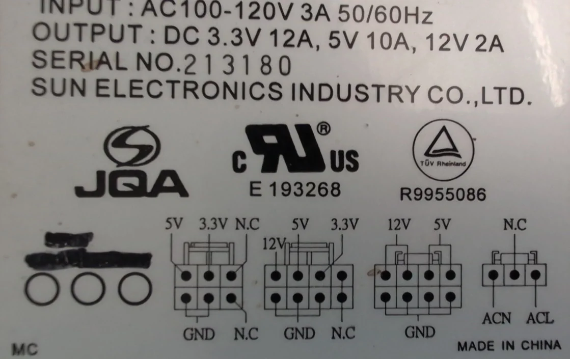
In this case, the plug I'll be utilizing is the third of the diagrams shown (the other two are reserved by the NAOMI.) With the voltage mapping, it's a simple matter of inserting a probe from my multimeter to determine the +5V rail that the HAS needs, which I then marked and pinned. Likewise, on the solder side of the HAS v5 is printed the pinout for the power input, similarly easy. Frankly, it's a simple matter either way, but knowing exactly where to look is just that much easier. (Before pinning the connectors, I enshroud the wires with wrap and heat shrink for the ends.) With the cord produced, the SUN PSU can act as the sole power provider to my NetDIMM Multi setup, avoiding any potential conflicts from using a discrete PSU for the HAS.
This post will contain details surrounding cap mapping and recapping a SUN model 400-5397-01 PSU, as well as the conversion of a U.S. standard power cord to provide power to it, and the creation of a custom cord to provide power to a HAS v5 supergun unit from the remaining PSU plug.
Recap Summary:
This information was previously posted in the Sun PSU cap map thread; however, in the interest of keeping that thread clean and on topic, I've moved the bulk of the 'story' over to its own thread here, and reformatted it so it's easier to read.
The SUN 400-5397-01 is- from everything I've read and seen- the gold standard PSU for the NAOMI. Moreover, it becomes critical equipment for NetDIMM operations, since JAMMA supplied power is insufficient. While other models (and ATX conversions) exist, the 400-5397-01 just works. Subsequently, I opted to pick one up for my NAOMI system since I wanted to eventually put together a NetDIMM multi. A good price for this PSU is about $50-$75, and I saved a search on eBay until I managed to find one in good looking condition that was described as having tested functional, which I bought for just shy of $68. I also ordered a recap kit for the 400-5397-01 from Arcade Parts and Repair.
When the PSU arrived, I tested its functionality and found it to be satisfactory; however, I had already intended to recap it, so I removed the cover and had a look at the interior. My decision wound up being a good choice, as a number of the electrolytic caps had indeed failed. This is where my inexperience at the time comes into play, and I made a silly mistake that cost me a lot of time and effort: Before verifying the cap kit I bought actually matched my hardware, I went through and desoldered all the caps on the unit, without documenting them, only noticing the mistake when the caps I went to replace them with weren't the same.
At that point, I began furiously looking through the forum. It was then I stumbled upon the SUN PSU Cap Map thread. I was unpleasantly surprised to learn that- not only did this PSU have several internal hardware revisions- I just happened to have a revision which hadn't been previously documented. So, not only had I foolishly purchased the wrong cap kit, but I also had only a limited knowledge of where the original caps actually went. At that point in my experience level, I was not meticulously documenting what I removed.
So, I decided to review all the information I did have to try and figure it out. Thankfully it went pretty well, actually:
- I managed to find a couple photos I had taken which had a few crucial capacitors in the background.
- Some capacitors failed in unique ways, which readily identified where they were on the board as a result.
- The PCB mount points have markings that are scaled to capacitor diameter, which allowed for comparison and exclusion.
- Finally, I simply remembered where a couple were.
The only ones I struggled with were the 4 x 1000uF 10V (colored black) and 1 x 1000uF 16V (colored blue) which occupy spots: C25, 26, 27, 28, and 32.
Initially, I didn't think I had any photos that would resolve the matter, which left me in the uncomfortable position of having to guess where the 16V went. However, after reviewing the available imagery again, I noticed I had one photo that just barely shows spot C27. In my perception, that small sliver of the cap in the light is decidedly blue (meaning the 16V). I asked a few others, and they also thought it appeared blue. That was enough to convince me that the 16V actually goes in C27, and the 4 x 10V subsequently occupy slots C25, 26, 28, and 32.
You can decide for yourself by having a look at the original photo and the two caps which I was struggling to differentiate (the top is a 10V and the bottom is the 16V):
|
|
The rest of the 1000uF 10V caps had clean tops. But the one that did happen to go? It went virtually identically to its cousin, as you can see- crazy coincidence, and also crazy annoying (because if they'd all been clean, or at least different, then there would be no question). In any event, it wound up being irrelevant. At that point I had managed to resolve the rest of the cap map, and I opted to simply bump the troublemakers all up to 16V to avoid the issue entirely.
Cap Map:
Code:
Manufacturer: Sun Electronics Industry Co., Ltd.
Model No.:    400-5397-01
Revision:     Unknown / Unspecified; characterized by dual, 18mm 470uF 200V capacitors, and parallel, vertically-oriented heat sinks.
Input:        AC100-120V, 3A, 50/60Hz
Output:       DC 3.3V 12A, 5V 10A, 12V 2A

Capacitor        Diameter    Qty     Location

1000uF 16V       10 mm       5       C25, C26, C27, C28, C32
4.7uF  50V       5  mm       2       C5, C6
470uF  200V      18 mm       2       C1, C2
1uF    50V       5  mm       1       C12
10uF   50V       5  mm       1       Fan Controller Daughter Board
330uF  10V       6  mm       1       C16
47uF   50V       8  mm       1       C11
470uF  10V       8  mm       1       C29
470uF  16V       8  mm       1       C30
680uF  10V       8  mm       1       C10
Conversion of U.S. Standard Wall Plug:
The 400-5397-01 is rated for AC input from 100-120V, 3A, at 50 or 60Hz. Standard wall outlet power in the U.S. falls within that range, and so- in my particular case- that means my unit can be converted to use a wall plug.
As far as getting power to the unit, at first I thought I might convert the box to a standard 3-prong panel mount and Dremel out a spot for it (which would make it more portable and cables pretty easy to find.) But, after some consideration and discussion, I determined to keep the original connector, so that it could be put back into a cab at will. Subsequently, I decided instead to modify a wall plug to use the PSU's native connector. A brief search on Amazon yielded a perfect cable with inline switch for this, from generic brand Filshu. I bought a couple to modify.
As for connectors, the PSU utilizes Amp Up connectors, with parts numbers as follows:
Code:
Part Name                           MFG #        DigiKey Part #
TE CONN PLUG HSG 3POS 3.96MM:       176272-1     A106282-ND
TE CONN RCPT HSG 3POS 3.96MM:       176283-1     A122360-ND
TE CONN TAB 16-20AWG CRIMP TIN:     175150-2     A100483CT-ND
TE CONN SOCKET 16-20AWG CRIMP TIN:  175152-2     A104081CT-ND
The PSU side utilizes the TE CONN PLUG HSG 3POS 3.9MM plug, with the TE CONN SOCKET 16-20AWG CRIMP TIN square female pins.
With the connectors and cord in hand, I went ahead and configured it for use with the power supply by pinning the connector with the wires matching the orientation of the connector coming from the PSU. The PSU does not have a ground wire, so instead I crimped on a fork to allow it to slot under a screw on the exterior of the PSU case. Once that was done, I put together a fresh connector for the PSU-side as well, since the old one was looking a little sad. I likewise refreshed the wires going to the fan control unit. Strictly speaking, this wasn't necessary, I just opted to since I was already in there.
With the power cord sorted, the PSU recapped, and everything in order, the job was done. It's been a while since I completed these modifications, and I've used the PSU now several times since then, and it's been rock solid. At the moment, I use it to power a NAOMI 2 NetDIMM WiPi NetBooter multi setup, along with HAS v5 supergun. While 2 of the unit's plugs connect to the NAOMI, a custom power cord I made draws 5V from the remaining plug to supply the HAS v5.
Power to HAS v5 Supergun Plug:
[ EDIT / UPDATE ]
This plug is not necessary. I only made it so I could have a "self-contained" setup, which didn't require any additional power sources (e.g. running the SUN to the NAOMI and a Meanwell to the HAS.) If you don't want to make one, you can simply use whatever power supply you regularly use with your HAS unit.
With that out of the way, one of the things I discovered when working with a few different I/O's is that I failed to take into account the power requirements of the I/O. Specifically, the audio amplification circuit, which may need 12V (e.g. in the case of TD-IO). For that reason, I later remade the cable with both 5V and 12V rails, and I would recommend you bear in mind the power considerations of your specific I/O setup when making your own solution.
[ END EDIT / UPDATE ]
This cord is intended to use the remaining power plug on the PSU to provide 5V to the HAS v5 supergun (which is what I have). The plug has both 5V and 12V rails (along with ground,) but the HAS unit only needs +5V and ground, so the cord will just be a simple 2-wire. Additionally, it will need a couple connectors, one for interfacing with the PSU and one to interface with the HAS.
Subsequently, I picked up the following:
Code:
- JST VH 3.96MM 6-PIN CONN (to HAS)
- TE CONN PLUG 8 POS NATURAL [PART #176275-1] (to PSU)
With everything in hand, it was time to get them pinned up. Thankfully, SUN has made it blissfully easy, and provided voltage mappings on the PSU:
In this case, the plug I'll be utilizing is the third of the diagrams shown (the other two are reserved by the NAOMI.) With the voltage mapping, it's a simple matter of inserting a probe from my multimeter to determine the +5V rail that the HAS needs, which I then marked and pinned. Likewise, on the solder side of the HAS v5 is printed the pinout for the power input, similarly easy. Frankly, it's a simple matter either way, but knowing exactly where to look is just that much easier. (Before pinning the connectors, I enshroud the wires with wrap and heat shrink for the ends.) With the cord produced, the SUN PSU can act as the sole power provider to my NetDIMM Multi setup, avoiding any potential conflicts from using a discrete PSU for the HAS.
Last edited: