

dillingerradio
Professional
Heya folks!
Time for another easy one!
This is the second in a trio of posts I've made on working on my NBA JAM T.E. The other two posts can be found here:
NBA JAM T.E. is a Midway T-Unit platform game, and in my case, consisted of the following two boards:
Equipment Needed:
The CPU board test passed with flying colors. Satisfied with its condition, I moved on with the recap.
I started with the audio board, since that's the more complex of the two.
Accessing all 22 of the caps on the audio board requires the removal of the heat sink. The heat sink is held in place by several means: it's slotted into the board via two tabs; it's affixed to the audio amp chip by way of two screws with nuts; it's vertically supported by a locking plastic PCB spacer; and it's got thermal paste between the heat sink and chip. I started with the gentle removal of the screws, which pass through two slots in the sides of the chip. After removing the screws, I lightly rocked the heat sink back and forth to break the old, hardened thermal paste free (dripping a bit of isopropyl alcohol between the chip and heat sink may assist this process if you're finding it to be stubborn). While working the heat sink free, I used my other hand and a set of needle nosed pliers to pinch the top of the plastic locking PCB spacer, and carefully manipulated it clear (it passes through the heat sink, making this process a little bit more difficult) After a bit of work, I was able to free the heat sink from the chip, and used isopropyl alcohol to clean the old thermal paste off both the chip and heat sink.
At this point it's important to be careful when manipulating and working on the audio board, due to the exposure of the chip and its vertical orientation.
With the heat sink removed, I moved on to the capacitors. I utilized a desoldering gun and removed what I could from the solder side of the board. Unfortunately, much of the solder had hardened from age, and was resistant to removal. On many, I had to cut the legs at the capacitors and complete the desolder from the parts side. Once done, I used some isopropyl alcohol to clean the mounting points of any contamination (a couple of the radial caps had "coffee stain" failures, which thankfully came up without issue).
With regards to the replacement capacitors, I used a pre-packaged kit from Arcade Parts and Repair. I've used several kits from them in the past, and they've always been excellent- this time was no different. I did notice a typo on their cap map- though- which identified the included 1uF as 100V, instead of the 63V that it was. But, it was irrelevant (either works). After verifying everything matched, I began the replacement.
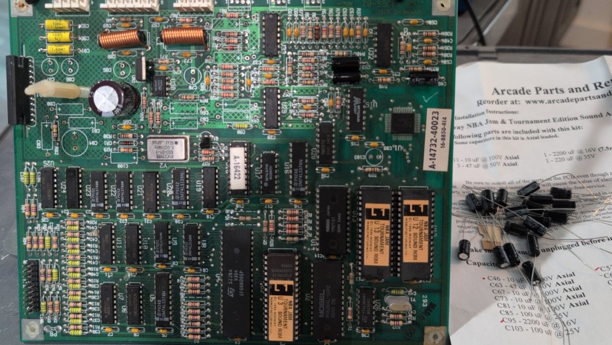
When placing capacitors I like to use a small blob of sticky-tac to hold each one in place. This helps ensure that when the board is turned for soldering they do not accidentally slide out. If you don't have any handy, it's not a problem- just verify the capacitor is fully seated before soldering. If one does back out a bit though, the remedy is a simple matter of pressing lightly on the offending leg while heating the joint until it passes through (and the capacitor is once more flush with the board.) Once the caps were in place and soldered I trimmed the legs. I cleaned the soldering flux from the board with an ultra-fine brush, rinsing in isopropyl alcohol.
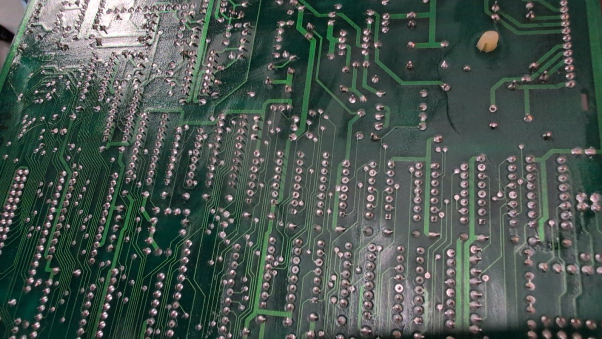
With the capacitors replaced, it was time to replace the heat sink. I had some nice, thin thermal pads leftover from some NVMe drives, one of which I repurposed and trimmed to the size of the heat sink contact patch. After affixing it to the heat sink I then used a pen to pop out the screw holes. It took some finagling overall, because the plastic locking PCB spacer on mine is a bit deformed, but I managed to reset the heat sink and get it screwed back onto the chip. Light screw pressure is enough to do the job, and some thermal pad material smooshing out confirms good contact. With the heat sink back in place, the job of recapping the audio board is complete.
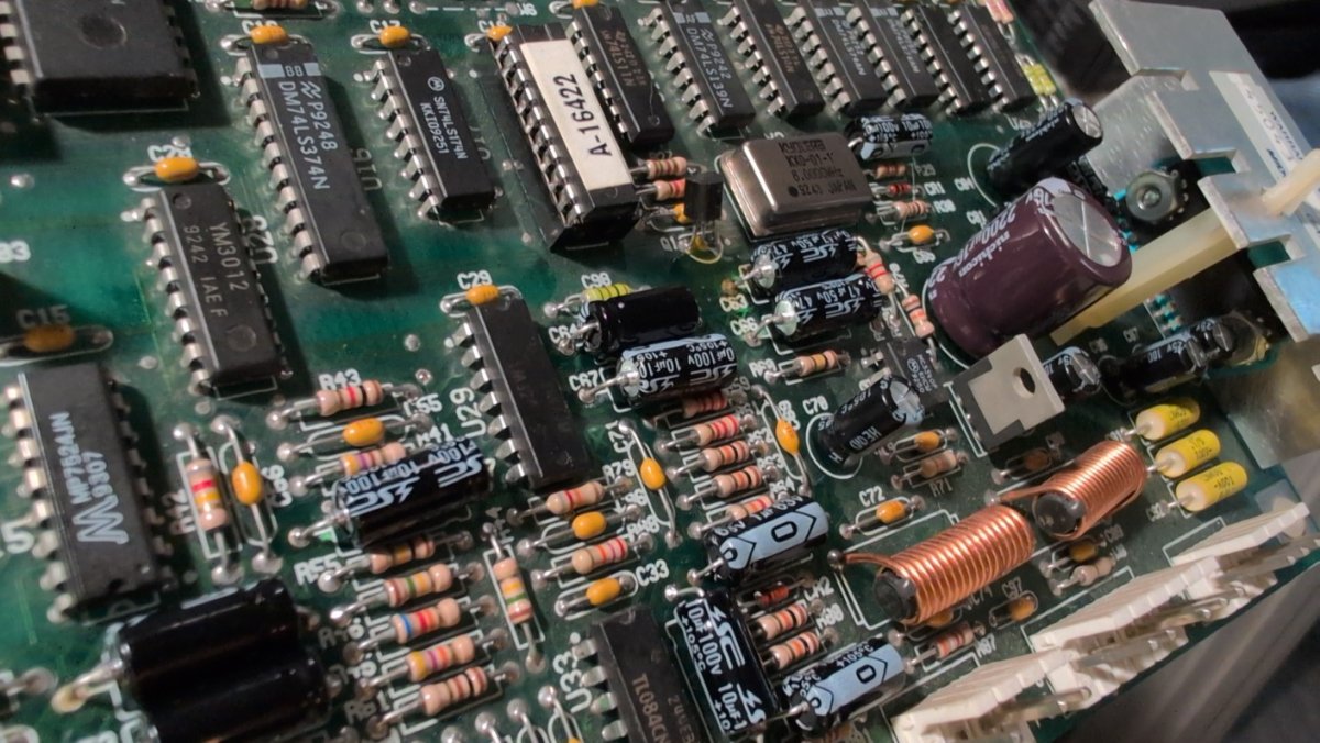
The CPU board followed next.
For the CPU board, the first step is removal. The CPU board features 15 caps, all axial. The solder for them was semi-resistant to removal, and while most came free with minor effort, a few were more resilient. For those, I wound up desoldering as normal, then using pliers to pull lightly on the capacitor from the parts-side while heating from the solder-side to completely free it. I then used my desolderer to clean up the pad on the parts-side. It's important to be especially careful when pulling resistant capacitors, to avoid potentially lifting the pad with the leg.
While a couple capacitors had visibly failed, between the two boards many of them didn't show any signs of failure until after they were removed (I circled some examples below). This reinforces the need to conduct regular, long-term, preventative maintenance on electrolytic capacitors. As far as the contamination from the failures, it was early enough to not have caused corrosion and came away with a bit of isopropyl alcohol. After a bit of cleaning, it was ready to move on to the next part: replacement.
Although Arcade Parts and Repair have a recap kit for the audio board, they do not specifically have a set for the CPU board. For that, I splurged a little and bought some new-old-stock 10uf 25V Philips 0K0 30's from eBay to make the CPU board an invisible repair.
I couldn't find my PCB stands, so I wound up soldering the CPU board on edge, much like the sound board. For large boards like this, I generally don't recommend this tactic. It's unwieldy, and made a little more difficult by the fact that the orientation means gravity isn't helping the solder flow into place. I suppose I could have leaned it back a bit more, but with my limited work space I opted instead to just push through. It's not a huge deal.
As I mentioned earlier, when soldering I generally use sticky-tac to stick the caps in place, and you can see that in practice below. While I couldn't find mine when I was originally doing the sound board, I did manage to find it for the CPU board. Once I set all the caps, I used a small ball of the sticky-tac to gently affix each one in place while I soldered the other side. Once done, I cleaned the solder side of flux with a soft-bristled brush and isopropyl alcohol, as before. Then I removed the sticky-tac from the parts side, and performed a bit of quick spot cleaning with the brush to finish things off.
The job is officially done at this point, and so I hooked the CPU back up to my rig to test its functionality and verify:
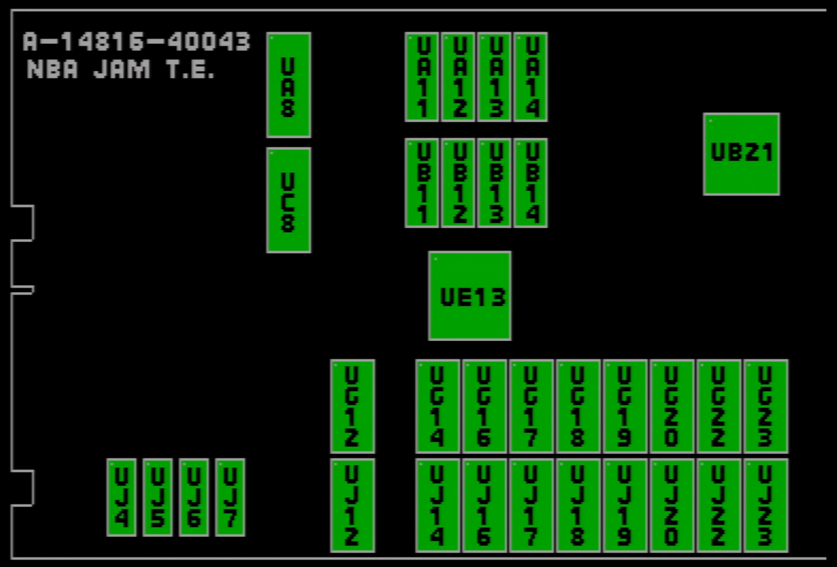
A bad cap isn't necessarily going to cause an obvious issue, but it's still good to check. I then booted the game and played a few rounds (while monitoring the board state) looking for issues. After a few minutes and no observable visual issues, I was satisfied that everything was in order.
EDIT:
Regarding the missing audio- the knob mod was on the way at the time of writing, and ultimately irrelevant to the process of a recap. Subsequently, it's covered in the final post that goes over the conversion from T.E. to S.E.
Time for another easy one!
This is the second in a trio of posts I've made on working on my NBA JAM T.E. The other two posts can be found here:
NBA JAM T.E. is a Midway T-Unit platform game, and in my case, consisted of the following two boards:
- The Midway A-14816-40023 CPU Board
- The Midway A-14732-40023 Audio Board
Equipment Needed:
- Soldering Iron
- Solder
- Flux
- Desoldering gun (or solder sucker/wick)
- Replacement capacitors
- Thermal paste or pad
The CPU board test passed with flying colors. Satisfied with its condition, I moved on with the recap.
I started with the audio board, since that's the more complex of the two.
Accessing all 22 of the caps on the audio board requires the removal of the heat sink. The heat sink is held in place by several means: it's slotted into the board via two tabs; it's affixed to the audio amp chip by way of two screws with nuts; it's vertically supported by a locking plastic PCB spacer; and it's got thermal paste between the heat sink and chip. I started with the gentle removal of the screws, which pass through two slots in the sides of the chip. After removing the screws, I lightly rocked the heat sink back and forth to break the old, hardened thermal paste free (dripping a bit of isopropyl alcohol between the chip and heat sink may assist this process if you're finding it to be stubborn). While working the heat sink free, I used my other hand and a set of needle nosed pliers to pinch the top of the plastic locking PCB spacer, and carefully manipulated it clear (it passes through the heat sink, making this process a little bit more difficult) After a bit of work, I was able to free the heat sink from the chip, and used isopropyl alcohol to clean the old thermal paste off both the chip and heat sink.
At this point it's important to be careful when manipulating and working on the audio board, due to the exposure of the chip and its vertical orientation.
With the heat sink removed, I moved on to the capacitors. I utilized a desoldering gun and removed what I could from the solder side of the board. Unfortunately, much of the solder had hardened from age, and was resistant to removal. On many, I had to cut the legs at the capacitors and complete the desolder from the parts side. Once done, I used some isopropyl alcohol to clean the mounting points of any contamination (a couple of the radial caps had "coffee stain" failures, which thankfully came up without issue).
With regards to the replacement capacitors, I used a pre-packaged kit from Arcade Parts and Repair. I've used several kits from them in the past, and they've always been excellent- this time was no different. I did notice a typo on their cap map- though- which identified the included 1uF as 100V, instead of the 63V that it was. But, it was irrelevant (either works). After verifying everything matched, I began the replacement.
When placing capacitors I like to use a small blob of sticky-tac to hold each one in place. This helps ensure that when the board is turned for soldering they do not accidentally slide out. If you don't have any handy, it's not a problem- just verify the capacitor is fully seated before soldering. If one does back out a bit though, the remedy is a simple matter of pressing lightly on the offending leg while heating the joint until it passes through (and the capacitor is once more flush with the board.) Once the caps were in place and soldered I trimmed the legs. I cleaned the soldering flux from the board with an ultra-fine brush, rinsing in isopropyl alcohol.
With the capacitors replaced, it was time to replace the heat sink. I had some nice, thin thermal pads leftover from some NVMe drives, one of which I repurposed and trimmed to the size of the heat sink contact patch. After affixing it to the heat sink I then used a pen to pop out the screw holes. It took some finagling overall, because the plastic locking PCB spacer on mine is a bit deformed, but I managed to reset the heat sink and get it screwed back onto the chip. Light screw pressure is enough to do the job, and some thermal pad material smooshing out confirms good contact. With the heat sink back in place, the job of recapping the audio board is complete.
The CPU board followed next.
For the CPU board, the first step is removal. The CPU board features 15 caps, all axial. The solder for them was semi-resistant to removal, and while most came free with minor effort, a few were more resilient. For those, I wound up desoldering as normal, then using pliers to pull lightly on the capacitor from the parts-side while heating from the solder-side to completely free it. I then used my desolderer to clean up the pad on the parts-side. It's important to be especially careful when pulling resistant capacitors, to avoid potentially lifting the pad with the leg.
While a couple capacitors had visibly failed, between the two boards many of them didn't show any signs of failure until after they were removed (I circled some examples below). This reinforces the need to conduct regular, long-term, preventative maintenance on electrolytic capacitors. As far as the contamination from the failures, it was early enough to not have caused corrosion and came away with a bit of isopropyl alcohol. After a bit of cleaning, it was ready to move on to the next part: replacement.
Although Arcade Parts and Repair have a recap kit for the audio board, they do not specifically have a set for the CPU board. For that, I splurged a little and bought some new-old-stock 10uf 25V Philips 0K0 30's from eBay to make the CPU board an invisible repair.
I couldn't find my PCB stands, so I wound up soldering the CPU board on edge, much like the sound board. For large boards like this, I generally don't recommend this tactic. It's unwieldy, and made a little more difficult by the fact that the orientation means gravity isn't helping the solder flow into place. I suppose I could have leaned it back a bit more, but with my limited work space I opted instead to just push through. It's not a huge deal.
As I mentioned earlier, when soldering I generally use sticky-tac to stick the caps in place, and you can see that in practice below. While I couldn't find mine when I was originally doing the sound board, I did manage to find it for the CPU board. Once I set all the caps, I used a small ball of the sticky-tac to gently affix each one in place while I soldered the other side. Once done, I cleaned the solder side of flux with a soft-bristled brush and isopropyl alcohol, as before. Then I removed the sticky-tac from the parts side, and performed a bit of quick spot cleaning with the brush to finish things off.
The job is officially done at this point, and so I hooked the CPU back up to my rig to test its functionality and verify:
A bad cap isn't necessarily going to cause an obvious issue, but it's still good to check. I then booted the game and played a few rounds (while monitoring the board state) looking for issues. After a few minutes and no observable visual issues, I was satisfied that everything was in order.
EDIT:
Regarding the missing audio- the knob mod was on the way at the time of writing, and ultimately irrelevant to the process of a recap. Subsequently, it's covered in the final post that goes over the conversion from T.E. to S.E.
Last edited:

