You are using an out of date browser. It may not display this or other websites correctly.
You should upgrade or use an alternative browser.
You should upgrade or use an alternative browser.
OpenJVS - JVS Emulator
- Thread starter bobbydilley
- Start date
I am sorry for dumb/redundant ask. I bought one chihiro type 3, so for SEGA race game I assume that you can use wheel PC & XBOX 360 compatible, or classic controller. Rumble/feedback works?
For gun game it's easy wiimote, but for ollie king controller pad is it good ? And for Namco race game?
For gun game it's easy wiimote, but for ollie king controller pad is it good ? And for Namco race game?
bobbydilley
Grand Master
Correct, you can use any USB controller, as long as you write the mapping file yourself.
Rumble/feedback is not currently supported as this is generally not part of JVS.
I haven't tried Ollie King myself, but I'm sure there is some way you can setup the controller to play it!
Feel free to join the discord chat below, there are tonnes of people on there that have probably already tried what you want to do")
https://discord.gg/aJAR9N2
Rumble/feedback is not currently supported as this is generally not part of JVS.
I haven't tried Ollie King myself, but I'm sure there is some way you can setup the controller to play it!
Feel free to join the discord chat below, there are tonnes of people on there that have probably already tried what you want to do
https://discord.gg/aJAR9N2
about feedback and rumble this sentence lead me into mistake, working in progress?Took me about 5 minutes to setup a map for this steering wheel - hoping to get started on the proper force feedback drivers soon!
bobbydilley
Grand Master
It is technically a 'work in progress' but I'm moving house soon so won't get much time to work on OpenJVS at the moment, so it's definately not going to be in a working state for a good while!
bobbydilley
Grand Master
Any normal big Raspberry Pi above a 2 should work fine.
I'm asuming you mean, can I install it on Windows 10? In which case no, OpenJVS is a Linux program and won't work on windows.
If you wanna ask anymore questions join here to save giving everyone notifications: discord.gg/aJAR9N2
I'm asuming you mean, can I install it on Windows 10? In which case no, OpenJVS is a Linux program and won't work on windows.
If you wanna ask anymore questions join here to save giving everyone notifications: discord.gg/aJAR9N2
Anyone tested OpenJVS with InitialD and Wangan Midnight - mainly with G25/29? Thanks!
Fredobedo007
Beginner
- Joined
- Jan 14, 2017
- Messages
- 9
- Reaction score
- 10
Gents,
Yes, I use openJVS with my G25 for initialD and I confirm it's working great!
I did have to install custom Logitech Drivers (new_lg4ff) to have Spring effect and be able to configure radius.
Yes, I use openJVS with my G25 for initialD and I confirm it's working great!
I did have to install custom Logitech Drivers (new_lg4ff) to have Spring effect and be able to configure radius.
bobbydilley
Grand Master
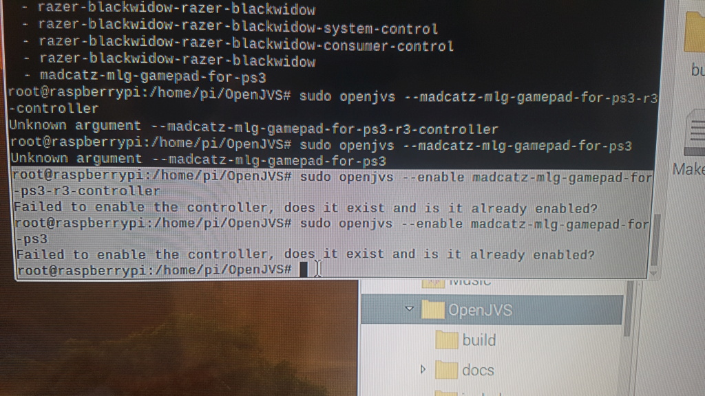
You’ve probably not made a map file for your controller right? It needs a file in /etc/openjvs/devices to know how to deal with the buttons, before you can enable it.
Come and ask on the discord chat if you need help with that
Come and ask on the discord chat if you need help with that
I asked this question on the discord but no answer maybe someone can help me here, so how to made someone can show his sense line little pcb and explain how to made one please for run openJVS with Chihiro. And ifII make one for chihiro no need made another for Naomi 2, etc.THX
II saw that on the web but it's so ugly, and I dont know if it run.

II saw that on the web but it's so ugly, and I dont know if it run.
@nonosto this is detailed on the OpenJVS github in an ASCIIMATIC.
https://github.com/OpenJVS/OpenJVS
In addition to the string of diodes, the red wire must also go a suitable GPIO pin on the RasPi.
https://github.com/OpenJVS/OpenJVS
In addition to the string of diodes, the red wire must also go a suitable GPIO pin on the RasPi.
DoktorSleepless
Professional
I think I have that same PCB. It doesn't work with OpenJVS. Or at least it didn't when I tried a couple of months ago.
THX I saw this graph but I dont know read that, if it's possiblee I need a real picture with finished PCB just to compare and undestand.@nonosto this is detailed on the OpenJVS github in an ASCIIMATIC.
https://github.com/OpenJVS/OpenJVS
In addition to the string of diodes, the red wire must also go a suitable GPIO pin on the RasPi.
Casselfornia
Student
I have the same one. It does run for me with Crazy Taxi in Naomi 2. But only if I boot the game with the standard JVS plug and then switch after boot to the RS485 one. When I go into the test menu my system freezes tho.I think I have that same PCB. It doesn't work with OpenJVS. Or at least it didn't when I tried a couple of months ago.
For initial D for example its not possible to do this, as it immediately displays an error message if you disconnect the JVS plug.
bobbydilley
Grand Master
I have replied on the discord @nonosto with a picture I drew.
The setup in the picture you sent won’t work at all - where did you find that? The sense line red wire MUST be also connected to GPIO 12 which is Pin 32 (by default) on the raspberry pi uninhibited by the diodes.
Basically it’s as simple as this:
Connect green wire to A
Connect white wire to B
Connect black wire to GND
Connect Red wire to Pin 32 on Pi
Connect Pin 32 to GND via a 1kOhm resistor or 4 signal diodes (make sure diodes are correct way around if used).
If anyone can suggest a better way of explaining please do!
Fredobedo007
Beginner
- Joined
- Jan 14, 2017
- Messages
- 9
- Reaction score
- 10
