What's new

Napoleon IV

Student
Joined
Aug 21, 2021
Messages
30
Reaction score
20
Location
Louisiana, USA
Hello,

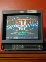
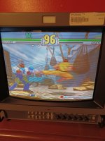
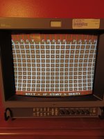
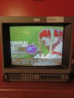
I am having a problem with my Sony PVM 14M4U monitor. It is in pristine condition and works wonderfully, except for one problem where the image is displaying extremely wide, so far so that it is cut off by the ends of the screen. The attached pictures show this. I was able to adjust the image through fiddling with degaussing in the menu and solve every problem except this. I believe it is suffering from pincushion distortion- something must not be regulating how wide the image is. My inability to adjust the width of the image through the degauss menu further supports this theory.

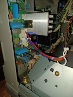
Would anyone know what could be what could be causing this, and how to fix it? I am a complete dummy when it comes to CRTs, and the information I have found through my own research online has all either been in Hindi or very poor English, or otherwise unclear. I will provide pictures of inside the CRT if that can help anyone diagnose what needs to be fixed.

Thanks!
 

Attachments

  • pincushion_1.jpg
    pincushion_1.jpg
    166.9 KB · Views: 317
  • pincushion_2.jpg
    pincushion_2.jpg
    202.1 KB · Views: 164
When you say menu, do you mean the standard menu or the service menu (requires a code to access)?
 
When you say menu, do you mean the standard menu or the service menu (requires a code to access)?
I don't know of any service menu. I know there are two menus: The regular one, which you just press "Menu" to access, and the degauss menu, which you press "Menu" and then "Degauss" and "Select" together, to access. I've fiddled in both with no avail for this problem.

Edit: It turns out the Degauss menu is the service menu, sorry about the terminology issue.
 
Last edited:
that's the service menu. adjust the hsiz parameter under NOR 60 DEF or something like that. turn off underscan before anything
 
that's the service menu. adjust the hsiz parameter under NOR 60 DEF or something like that. turn off underscan before anything
I've done this. I actually get a super clear image when the H Size setting under NOR 60 DEF is set to 40 or below. Above that it appears that the scanlines don't line up correctly. Underscan was on in the first two pictures I posted, but after turning it off and adjusting afterwards, the problem persists. Here's some more pictures after taking those advice.
 

Attachments

  • 20220222_205108.jpg
    20220222_205108.jpg
    186.9 KB · Views: 120
  • 20220222_205052.jpg
    20220222_205052.jpg
    177.7 KB · Views: 241
Sorry it's been a while since I had time to look at this. This morning I took the cover off so I could get a look at the inside, or as best as I could. To get a better glance at the motherboard, I would have to discharge the whole TV, but I don't think I have the proper equipment to do so yet. I believe I've found the problem, but I'm not 100% sure- in the bottom left corner of the motherboard, there's a capacitor that seems to have some sort of acidic liquid coming out, and something that's torn on the bottom of it, I assume that this is what's causing the issue. Whether or not this is in the part of the motherboard that handles the H size of the video, I'm not sure, so if anyone knows where I can find a schematic of this TV's motherboard, that would help a lot.
 

Attachments

  • suspect.jpg
    suspect.jpg
    675.3 KB · Views: 145
Last edited:
I think I might have a 14M2 with the same problem

The issue seems to be that the OSD for the service menu (the degauss menu) DISPLAYS the setting changes as expected.
But the signals are not actually being sent to the deflection coil to change the geometery.

Established wisdom seems to be as follows, stiched together from other parts of the internet. There is a bit of reading in here, but my summary is as follows

Desolder L509 - if the picture shrinks back to normal then investigate Q503 or Q501 or (and we hope not!) IC509
https://www.reddit.com/r/crtgaming/comments/mz5z7d/so_took_my_pvm_14m4_out_of_storage_but/

If the picture stays the same with L509 desoldered then investigate the diodes, start with D512 and work through his local buddies (D502, 506 and etc)
https://shmups.system11.org/viewtopic.php?f=6&t=69677

It might also be worth looking at C514, C2510

If you dont already have one of these it's worth the $20. Tonnes of fun and useful for this kind of thing
https://www.amazon.com/Multifunctio...9&sr=1-2-ed8a42d3-65f1-4884-a3a2-0dd6e83b6876
It is by no means a precision tool, but helpful to check if (for example) a diode has burned out or a transistor has gone bad...
I'm not recomending this specific one, it was just the first search result.

I'll actually be doing this in the next few days because my monitor has the same problem - if you want to work together on this let me know and I'll post lots of stuff here.
 
I think I might have a 14M2 with the same problem

The issue seems to be that the OSD for the service menu (the degauss menu) DISPLAYS the setting changes as expected.
But the signals are not actually being sent to the deflection coil to change the geometery.

Established wisdom seems to be as follows, stiched together from other parts of the internet. There is a bit of reading in here, but my summary is as follows

Desolder L509 - if the picture shrinks back to normal then investigate Q503 or Q501 or (and we hope not!) IC509
https://www.reddit.com/r/crtgaming/comments/mz5z7d/so_took_my_pvm_14m4_out_of_storage_but/

If the picture stays the same with L509 desoldered then investigate the diodes, start with D512 and work through his local buddies (D502, 506 and etc)
https://shmups.system11.org/viewtopic.php?f=6&t=69677

It might also be worth looking at C514, C2510

If you dont already have one of these it's worth the $20. Tonnes of fun and useful for this kind of thing
https://www.amazon.com/Multifunction-transistor-Capacitor-Inductance-screwdriver/dp/B071Y5CHPK/ref=sxin_13_ac_d_mf_br?ac_md=4-3-a3VtYW4=-ac_d_mf_br_br&cv_ct_cx=Component+Tester&keywords=Component+Tester&pd_rd_i=B071Y5CHPK&pd_rd_r=31d3509c-7d62-4fa1-b95e-d001bce48790&pd_rd_w=dJa2u&pd_rd_wg=X2kz7&pf_rd_p=af56c395-f6ae-4741-98f7-37d0cc7c93ab&pf_rd_r=NENKN2T39W5MNDTC5FG0&psc=1&qid=1645939929&sr=1-2-ed8a42d3-65f1-4884-a3a2-0dd6e83b6876
It is by no means a precision tool, but helpful to check if (for example) a diode has burned out or a transistor has gone bad...
I'm not recomending this specific one, it was just the first search result.

I'll actually be doing this in the next few days because my monitor has the same problem - if you want to work together on this let me know and I'll post lots of stuff here.
Well, I was going to just return it and buy a different one on Ebay, but now that you've shown your support I think I'll go ahead and just fix this one up. The information you've provided looks good.

The first logistical problem is getting parts. There's a seller on Ebay who sells an entire motherboard's worth of parts (without the motherboard itself), for these kinds of TVs, though I want to make sure this is legit. Here's the link, can anyone tell me if anything looks wrong about this?

And, is the meter tool you have there necessary for this job? I'll buy it if so, but I'm saving money for the steam deck at the moment, so "spending for fun" is a little short right now... :)

Lastly, I'm not entirely sure how I'm supposed to ground the screwdriver for the anode cap detaching process. The videos I've seen said to tie a copper wire to it, and hook it to a metal casing, but they spoke as if this was something already understood to the viewer, so I'm not entirely sure how this would go. Is there a special copper wire I need for this? Any tips?
 
He's a reputable seller. A previous Sony tech specializing in PVMs and BVMs. But what he typically provides are a list of capacitors most likely to fail, along with the caps. But if you buy from him, he's always happy to walk you through any questions you have on the phone (such as recalibrating after replacing the caps).

I wouldn't say a multimeter is a requirement for recapping, unless you rip a pad and need to find a suitable replacement spot to solder to.

To make a discharge tool, this could work:
View: https://www.youtube.com/watch?v=JeX5Y7Amk0o


And for the process of discharging:
View: https://www.youtube.com/watch?v=0X28FX_XxtU
or
View: https://www.youtube.com/watch?v=1CVXzlkOjGg
 
The first logistical problem is getting parts. There's a seller on Ebay who sells an entire motherboard's worth of parts (without the motherboard itself), for these kinds of TVs, though I want to make sure this is legit. Here's the link, can anyone tell me if anything looks wrong about this?
Savon Pat is a legend in the PVM/BMV industry - that kit that he sells is a Capicator kit its drop-in replacement for most unreliable caps (I think there are about 20 caps in the kit). Some people on the internet say that the caps in that kit are not of the higest quality - but really what you are buying is the knowledge and support so its probably worth it
And, is the meter tool you have there necessary for this job? I'll buy it if so, but I'm saving money for the steam deck at the moment, so "spending for fun" is a little short right now... :)
Since we dont know exactly whats wrong there are two options - option 1 is to randomly replace stuff and hope. Option 2 is to find out what it wrong and fix that. Option 1 is actually quite effective in a lot of cases :) For example how will we know if a transistor is bad? Plug it in and hit the button... https://www.arcade-projects.com/threads/namco-exceleena-1-2-cabinets.13302/post-278310
 
I've gotten the multimeter in the mail, still waiting on the repair kit. I'm looking to open the CRT up and start testing to see which capacitors are dead. How do I do this? And also, when making the discharge tool, where is a "ground point" that I can attach the wire to?
 
The videos I linked to show points to clip onto.

To test capacitors I believe you need to remove them from the circuit (desoldered). Someone correct me if I'm wrong.

Edit: changed typo from remind to remove
 
Last edited:
yes, you need to remove them and short the pins with a screwdriver or metal object to discharge them - unless you want to damage the tester!
a multimeter wont help much - to test a cap you need to test capacitance and ESR.
i use a component tester for that.
 
I've gotten the multimeter in the mail, still waiting on the repair kit. I'm looking to open the CRT up and start testing to see which capacitors are dead. How do I do this? And also, when making the discharge tool, where is a "ground point" that I can attach the wire to?
Whoops, had forgotten about this - got sidetracked.

To answer your question I made these videos a while back but never uploaded them

CRT discharge tool - it is not fancy

How to use a CRT discharge tool on a PVM

So to answer your questions directly
1) you'll need to remove the capicators to test them. it's possible to get specialist tools that can test caps "in circuit" but those cost a lot of money
2) any part of the metal chassis will be find. obviously dont hold onto the chassis while you are discharging the CRT through it.

I'll make another video tonight showing how to dismantle a PVM 14M2 into the "service position" so we can start work on it
 
I did the disassembly tonight and made some videos as I went - these are at the same level of quality you have come to expect from me :)

14M2 video showing initial problem (screen massively stretched, pincushion stick, service menu responds but does not change the geometery

14M2 remove cover

14M2 remove power supply and discharge anode

14M2 remove neckboard and rear panel

14M2 remove anode cup

Next we need to pull out the a board
 
Continuing from before

14M2 pull out A board

14M2 extract A board from plastic tray so we can work on it

At this point we are ready to start work on the A board
 
The horizontal width, pincushion, and unresponsive service menu controls are all coming from the same place

The geometry IC thinks it is controlling horizontal width (and all of the other associated settings in the horizontal geometery section) - but really all it's doing is updating the counter on the screen. The horizontal geoemtery control section is sending whatever signals it damn well likes, and by default that is massively wide and exaggerated pincushon

So the fault is somewhere in the (absurdly overcomplicated) horizontal geometry section. There is a diagram on page 60 of the service manual if you want to work through it - but this is a common enough problem with PVM's that the troubleshooting flowchart is well known

First remove L509 - this will stop the horizontal geometery control section sending anything at all

If the screen shrinks back to normal size when I509 is removed then the fault is (in order of probability)
Q503
Q501
IC509

If the screen is still wide when I509 is removed then the fault is (in order of probability)
D512
D502
D506

So I removed I509 and - happy days! The screen is now back at normal size.
IMG_0058.jpg

Next steps from here are to test Q503, then Q501
 
And a video showing the change

Old - massively stretched

with L509 removed - no longer massively stretched now check Q503/Q501
 
Back
Top