
- Low-frequency oscillation / "motorboating"
You are using an out of date browser. It may not display this or other websites correctly.
You should upgrade or use an alternative browser.
You should upgrade or use an alternative browser.
Project: Helper board for Mitsu's Repro Batman Forever Sound amp board
- Thread starter mathewbeall
- Start date

mathewbeall
Enlightened
HAHAHAHAHHAAH - not the term I would generally use - but it IS a good description for the sound it was making!

mathewbeall
Enlightened
Update - the next round of boards should ship tomorrow from JLCPCB - so I would expect to get them Saturday, so I can do some testing with what is hopefully the final board rev. Just need to fix that one downmixing issue I noticed and we will be good!
mathewbeall
Enlightened
Another small update - I should get the boards Thursday and can test. I have all the parts for the full 24 board run EXCEPT for the 4PDT switches - I just had to order 75 of them again from aliexpress - they cancelled my previous order due to inactivity..  . They are listed with like 10,000 in stock - so not sure what is going on - really hope that part doesn't become an issue because it was hard to actually find that switch, and now I need that exact footprint. Will keep everyone updated at least to the testing for the audio fix.
. They are listed with like 10,000 in stock - so not sure what is going on - really hope that part doesn't become an issue because it was hard to actually find that switch, and now I need that exact footprint. Will keep everyone updated at least to the testing for the audio fix.
channelmaniac
Professional
Try Tayda Electronics. They are popular with the DIY Synthesizer crowd.
https://www.taydaelectronics.com/catalogsearch/result/?q=4pdt
https://www.taydaelectronics.com/catalogsearch/result/?q=4pdt
mathewbeall
Enlightened
None of those look quite like the one I got (and fits the boards I just made) - 2X6Try Tayda Electronics. They are popular with the DIY Synthesizer crowd.
https://www.taydaelectronics.com/catalogsearch/result/?q=4pdt
https://www.aliexpress.us/item/2251801767074174.html
I am hoping they just ship the 75 I need, and I'll be good...

mathewbeall
Enlightened
Got the boards a day early!
Did some testing with JUST the mono downmixing circuit tonight - so power to the amp board, and then amplified signal back to the helper board, downmixing to Mono (Taito method) but with resistors between the output leg and the JAMMA edge - this seems to have solved the weird issue I was hearing where the audio would distort or have a weird feedback resonance loop when the amps were cold - I ran it for about an hour tonight, and would let it cool down (after a game play) and then start it again, etc. NO issues. The one caveat is that I am not actually driving speakers with it - its going to a supergun, and then out via SCART to my tink4k and into my TV. The amps do get a little warm doing it this way, but not too hot to touch (at all) - I am sure this isn't the most efficient way to mix stereo down to mono - but it seems to work.
I will take this setup to work where I have a cabinet with actual speakers in it off the jamma edge, and hook this up and make sure it sounds ok there driving actual speakers.
I will get the rest of the board built out this weekend and test all the different things (12v fans, voltmeter, live level input/output/volume adjust) and as long as those all pass (no reason they shouldn't) - then I think we are good to go - after I get the 4PDT switches!
Matt
Did some testing with JUST the mono downmixing circuit tonight - so power to the amp board, and then amplified signal back to the helper board, downmixing to Mono (Taito method) but with resistors between the output leg and the JAMMA edge - this seems to have solved the weird issue I was hearing where the audio would distort or have a weird feedback resonance loop when the amps were cold - I ran it for about an hour tonight, and would let it cool down (after a game play) and then start it again, etc. NO issues. The one caveat is that I am not actually driving speakers with it - its going to a supergun, and then out via SCART to my tink4k and into my TV. The amps do get a little warm doing it this way, but not too hot to touch (at all) - I am sure this isn't the most efficient way to mix stereo down to mono - but it seems to work.
I will take this setup to work where I have a cabinet with actual speakers in it off the jamma edge, and hook this up and make sure it sounds ok there driving actual speakers.
I will get the rest of the board built out this weekend and test all the different things (12v fans, voltmeter, live level input/output/volume adjust) and as long as those all pass (no reason they shouldn't) - then I think we are good to go - after I get the 4PDT switches!
Matt
Last edited:

9999 Damage
Grand Master
I'm in!

mathewbeall
Enlightened
Everything checks out! Do most people intend to mount the PCB board above (like I have) or very close to the ST-V board? I would like to standardize on the length of the power and amplified audio cables that go between the helper-board and the amp board. For my setup - since its mounted above, i can get away with pretty small lengths. What is everyone else going to be doing?
Also - should I include the low-level input/output harnesses, with bare wire on the other end? That lets people wire up their own RCA jacks depending on how they will hook it up? I am thinking maybe .5 meter?
Let me know what everyone thinks - if we can standardize on that, I can start making the cables while I am waiting for the 4PDT switches to come in.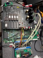
Also - should I include the low-level input/output harnesses, with bare wire on the other end? That lets people wire up their own RCA jacks depending on how they will hook it up? I am thinking maybe .5 meter?
Let me know what everyone thinks - if we can standardize on that, I can start making the cables while I am waiting for the 4PDT switches to come in.
mathewbeall
Enlightened
Thats right, I didn't post that small kit yet to mount it.
I used M3 - 50mm standoffs for this kit, I went with metal for the extra rigidity. the pieces SHOULD be self explanatory.
https://www.thingiverse.com/thing:7328505
I used M3 - 50mm standoffs for this kit, I went with metal for the extra rigidity. the pieces SHOULD be self explanatory.
https://www.thingiverse.com/thing:7328505
RepairGuy95
Champion
I will probably go above but upside down.
@clintkolodziej designed a mount for the sound board. I would take that into consideration since that would be a standardized mount, in a sense.Everything checks out! Do most people intend to mount the PCB board above (like I have) or very close to the ST-V board? I would like to standardize on the length of the power and amplified audio cables that go between the helper-board and the amp board. For my setup - since its mounted above, i can get away with pretty small lengths. What is everyone else going to be doing?
Also - should I include the low-level input/output harnesses, with bare wire on the other end? That lets people wire up their own RCA jacks depending on how they will hook it up? I am thinking maybe .5 meter?
Let me know what everyone thinks - if we can standardize on that, I can start making the cables while I am waiting for the 4PDT switches to come in.

The flat cable that comes with the sound pcb is a certain length so I would make my other cable lengths considering the pcb would be mounted in a cab with the pcbs next to each other. That would be the max length and would also be compatible for anyone who stacks their pcbs instead.
RepairGuy95
Champion
That's a good idea.
A little extra for all possibilities.
A little extra for all possibilities.
I don't have the sound board yet, so I'm not entirely sure what my final setup will look like. Since my STV board has the Lions3 Dark Knight acrylic case, I'll probably place it next to it rather than on top, if that makes sense? Hope this helps.Everything checks out! Do most people intend to mount the PCB board above (like I have) or very close to the ST-V board? I would like to standardize on the length of the power and amplified audio cables that go between the helper-board and the amp board. For my setup - since its mounted above, i can get away with pretty small lengths. What is everyone else going to be doing?
Also - should I include the low-level input/output harnesses, with bare wire on the other end? That lets people wire up their own RCA jacks depending on how they will hook it up? I am thinking maybe .5 meter?
Let me know what everyone thinks - if we can standardize on that, I can start making the cables while I am waiting for the 4PDT switches to come in.
mathewbeall
Enlightened
The 40 pin cable? I ended up buying a smaller length for mine so am not sure what the original cable length of that is - but yes, I could work with that length as thats a common component. Can someone measure how long the 40 pin cable is and let me know?The flat cable that comes with the sound pcb is a certain length so I would make my other cable lengths considering the pcb would be mounted in a cab with the pcbs next to each other. That would be the max length and would also be compatible for anyone who stacks their pcbs instead.