It seems this board came originally from Italy, look at the text "CAFAGGI" on the rounded sticker.Cafaggi was a big italian distributor/importerYes you need 12 * 27C040.And there's a mistake, the resistor is 2 ohm but can be substituted by a piece of wire.While googling for the IC's needed I stumbled upon this post in which our friend @Apocalypse explains the conversion.
My French is not great, but in any case it states you need 12x EPROM type 27C040, but also a 10k resistor?
Can anyone confirm if this is still needed?
He also says there are 2 versions of the Squash PCB (922804/1 et 922804/2) and he only confirms the latter is working and can't guarantee that the first revision works.
Any info on this would be appreciated")
I'm not sure what is the difference between 922804/1 and 922804/2 but they look visually identical.
[EDIT]
Here's my converted board:

And a video of it running:
You are using an out of date browser. It may not display this or other websites correctly.
You should upgrade or use an alternative browser.
You should upgrade or use an alternative browser.
Released: Gaelco Conversions. Squash or Thunder Hoop into Biomechanical Toy
- Thread starter Darksoft
- Start date
Sp33dFr34k
Champion
Thanks for the explanation.
So basically 12 roms, switch the resistor in G4 from the right to the left, and put a 2ohm resistor or a piece of wire in PA4. That is indeed a minimal hardware change
So basically 12 roms, switch the resistor in G4 from the right to the left, and put a 2ohm resistor or a piece of wire in PA4. That is indeed a minimal hardware change
A
Apocalypse
Yep I saw that too. I bought it last year in France.It seems this board came originally from Italy, look at the text "CAFAGGI" on the rounded sticker.Cafaggi was a big italian distributor/importer
You got it!Thanks for the explanation.
So basically 12 roms, switch the resistor in G4 from the right to the left, and put a 2ohm resistor or a piece of wire in PA4. That is indeed a minimal hardware change
The hardest part is removing the eproms that are soldered into the pcb. They are a huge pain without the proper equipment. Two should already be socketed. I was trying to determine the resistor value and when I found it to be 2 ohm I was surprised. 2 ohm is protecting nothing. LOL. So I just used a wire strip like Apocalypse mentioned.
Squash is not a terrible game. Played it quite a bit before converting it. But BT is a much more interesting game.
Squash is not a terrible game. Played it quite a bit before converting it. But BT is a much more interesting game.
Sp33dFr34k
Champion
True, too bad it's not thát easily reversible otherwise you could've just swapped back the roms whenever you felt like playing squash againSquash is not a terrible game. Played it quite a bit before converting it. But BT is a much more interesting game.
Im gonna install sockets, you know, so when I feel like playing Squash I can easily swap the romsTrue, too bad it's not thát easily reversible otherwise you could've just swapped back the roms whenever you felt like playing squash againSquash is not a terrible game. Played it quite a bit before converting it. But BT is a much more interesting game.
jk i dont think I will ever play this squash game again 
A
Apocalypse
As said just install sockets. That's what I did (see picture above).True, too bad it's not thát easily reversible otherwise you could've just swapped back the roms whenever you felt like playing squash againSquash is not a terrible game. Played it quite a bit before converting it. But BT is a much more interesting game.
Sp33dFr34k
Champion
That's what I was planning to do, but I take it you need to switch the resistor back as well
Yep but if you are creative you can install a solder free method for changing the jumpers.That's what I was planning to do, but I take it you need to switch the resistor back as well
A
Apocalypse
Exactly.
And only one resistor has to be moved back. The second one @ PA4 can be left in place no problem.
And only one resistor has to be moved back. The second one @ PA4 can be left in place no problem.
xodaraP
Legendary
Indeed they are, but this conversion uses 4mbit 27C040 EPROMs, not 8mbit ")
I love the art style of this game, does it remind anyone else of Earthworm Jim?
I love the art style of this game, does it remind anyone else of Earthworm Jim?
Yes like a Jersey Shore Earthworm Jim on acid.I love the art style of this game, does it remind anyone else of Earthworm Jim?
mr3xtraball
Student
Hello,
First of all i want to say thankyou to Darksoft, neocps1, and many other who made possible and available in the wild this conversion (biomechanical toy)
Now, i had a go to make myself a biomechanical toy game conversion.I have a Thunder Hoop pcb laying around, and i had a stab at converting it. All the work with ROMs/EEPROMs/sockets/programming went ok. But later in the process i noticed that my pcb was silkscreened "REF:922804/1"then i said to myself-im fucked up !
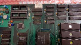
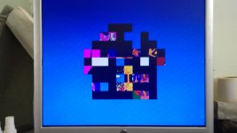
I have fired up the board and indeed i was fucked up, the graphics were "corrupted".I am assuming that Thunder Hoop REF:922804/1 and Squash REF:922804/2 are not fully compatible.I will post a few pics showing my pcb (pls ignore the empty sockets on the sound section-i ran out of 4001's),and the graphic "corruption".
I also noticed that my pcb REF:922804/1, is missing a set of jumpers at the location G2/G3/G4/G5,
which pcb REF:922804/2 has them.Could be that the jumpers that selects the encrypted/not encrypted video RAM ?
My question is : anyone has experienced the issues i have ?, anyone has done the conversion on
Thunder Hoop REF:922804/1 pcb ? Does anybody know where the wires from jumpers at location G2/G3/G4/G5 are routed to ?
Thanks in advance for any help/hints, Dragos.


First of all i want to say thankyou to Darksoft, neocps1, and many other who made possible and available in the wild this conversion (biomechanical toy)
Now, i had a go to make myself a biomechanical toy game conversion.I have a Thunder Hoop pcb laying around, and i had a stab at converting it. All the work with ROMs/EEPROMs/sockets/programming went ok. But later in the process i noticed that my pcb was silkscreened "REF:922804/1"then i said to myself-im fucked up !
I have fired up the board and indeed i was fucked up, the graphics were "corrupted".I am assuming that Thunder Hoop REF:922804/1 and Squash REF:922804/2 are not fully compatible.I will post a few pics showing my pcb (pls ignore the empty sockets on the sound section-i ran out of 4001's),and the graphic "corruption".
I also noticed that my pcb REF:922804/1, is missing a set of jumpers at the location G2/G3/G4/G5,
which pcb REF:922804/2 has them.Could be that the jumpers that selects the encrypted/not encrypted video RAM ?
My question is : anyone has experienced the issues i have ?, anyone has done the conversion on
Thunder Hoop REF:922804/1 pcb ? Does anybody know where the wires from jumpers at location G2/G3/G4/G5 are routed to ?
Thanks in advance for any help/hints, Dragos.
Attachments
A
Apocalypse
@mr3xtraball isn't it related to this:
I'm not sure of it.If you look at MAME's source you can see one of the decryption parameter is different between Squash and Thunder Hoop.As a donor you can use squash and thunder hoop. I'm pretty confident that Big Karnak can also be used but this is uncorfimed yet.
For Squash param1 = 0x0f and 0x0e for Thunder Hoop
xodaraP
Legendary
Interested in this myself. I saw earlier in the thread that Thunder Hoop is a /1 and Squash is a /2 in the MAME driver.
I assumed both were compatible from the topic and assumed others had used the /1 board - though I did see Apocalypse mentioned there is a parameter difference.
The board I have arriving is a /1 board, so hopefully I can use it
I assumed both were compatible from the topic and assumed others had used the /1 board - though I did see Apocalypse mentioned there is a parameter difference.
The board I have arriving is a /1 board, so hopefully I can use it
xodaraP
Legendary
@mr3xtraball - I notice that there's 4 jumpers on the board to set ROM sizes - 2 are above your graphics ROMs and 2 are next to your sound ROMs.
These are to set 4mbit/8mbit ROM sizes - it makes little sense to me that there's 2 jumpers to set 8 ROMs for graphics, but also 2 jumpers to set 2 sound ROMs?
Is it possible one of the 2 jumpers next to the sound is related to graphics? Or is it possible there's another set of jumpers I'm not seeing?
I don't see anything, but I also don't have my board yet, but hopefully the /1 boards aren't a complete non starter, that would be upsetting
mr3xtraball
Student
Hello,
Thanks for the response.
Indeed i have looked at mame's gaelco driver and @apocalipse is right: the two decryption parameters are different, For Squash = 0x0f and Thunder Hoop =0x0e.
My guess is that those different parameters(values) are hard-coded in those 2 fpga's, or by pcb design (wire routing/ extra jumpers), or by 68k's program, im no expert in gaelco hardware.
@xodaraP , i guess that two boards are incompatible, so its possible to be upsetting for you, as it was for me.
It would be very helpful that someone with a REF:922804/2 board would pinpoint the four wires which forms the extra jumpers not found on REF:922804/1 board , to see where it leads to which IC's to determine the differences in those boards.
My REF:922804/1 board, has only 2 sets of jumpers: one set for setting graphics ROMs, and the other for setting the sound ROMs
Have a good day, Dragos.
Last edited: