Bought this as a broken chassi. A previous owner (not the one I got it from) had done a recap and after that the chassi had stopped working.
This repair was quite easy but I post this log anyways because complete repair logs with ms2931 are scarce and I also wanted to share some advice and information with the community.
I tried to start up. B+ couldn't stabilize but was slowly increasing. Then B+ went up way above 180VDC and the chassi did trip. Please note that turning B+ up is how the protection circuit force the chassi to turn off.
Disconnected the fuse to the HV-supply. No change.
Looked into the power section and spent a lot of time to investigate the photo coupler feedback circuit. I did consult an AI which gave me several stupid/dangerous advices.
By the way; manual says to look for 130vdc at C905 on the primary side. I got 150 vdc. This confused me for a while but then I remembered the electricity lessons from school: Vrectified = Vac*✓2
I ran at 110VAC: 110*✓2≈155vdc.
90VAC which is the minimum approved input voltage gives: 90*✓2≈130vdc.
Put in a bulb and now I got a steady B+. For about 3 seconds before the protection circuit tripped.
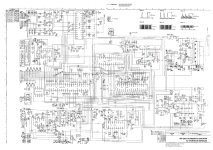
This was an enough time span to measure alla secondary voltages. They were all present. (I did some work on the somewhat blurry schematic and placed out measuring points, marked in red. Attached it here in this post. Please be warned: following this schematic will get you killed and your home will burn down)
Examined the soldering job: Led-free solder. Five broken pads - three of them had no proper connection. Fixed these.
While removing one capacitor I managed to lift one pad myself. I've done some circuit board repairs over the years - but boy these PCBs are sensitive! I lowered my soldering iron from 350 to 330 grC and stopped using solder sucker.
Turned on the power and no tripping. Put in the hv-fuse and the screen fired up. Green was missing except in the OSD.
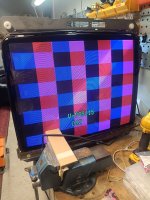
Took a look around the video input circuitry and found a hairline piece of solder shorting one of the SMD capacitors. Removing this got the green fully working.

Cleaned up leaked black compound from L512.
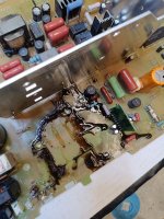
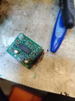
Found that the 2200uf capacitor @ c923 had been replaced with a 680uf. LOL!
Replaced some old capacitors that had been left unchanged the last time including the two important smd-caps on u701. (Why on earth don't they sell complete cap kits?)
Well. Now all caps are changed. Chassi is working. The official service manual is a great source when trouble shooting - if you take your time to really read it.
This repair was quite easy but I post this log anyways because complete repair logs with ms2931 are scarce and I also wanted to share some advice and information with the community.
I tried to start up. B+ couldn't stabilize but was slowly increasing. Then B+ went up way above 180VDC and the chassi did trip. Please note that turning B+ up is how the protection circuit force the chassi to turn off.
Disconnected the fuse to the HV-supply. No change.
Looked into the power section and spent a lot of time to investigate the photo coupler feedback circuit. I did consult an AI which gave me several stupid/dangerous advices.
By the way; manual says to look for 130vdc at C905 on the primary side. I got 150 vdc. This confused me for a while but then I remembered the electricity lessons from school: Vrectified = Vac*✓2
I ran at 110VAC: 110*✓2≈155vdc.
90VAC which is the minimum approved input voltage gives: 90*✓2≈130vdc.
Put in a bulb and now I got a steady B+. For about 3 seconds before the protection circuit tripped.
This was an enough time span to measure alla secondary voltages. They were all present. (I did some work on the somewhat blurry schematic and placed out measuring points, marked in red. Attached it here in this post. Please be warned: following this schematic will get you killed and your home will burn down)
Examined the soldering job: Led-free solder. Five broken pads - three of them had no proper connection. Fixed these.
While removing one capacitor I managed to lift one pad myself. I've done some circuit board repairs over the years - but boy these PCBs are sensitive! I lowered my soldering iron from 350 to 330 grC and stopped using solder sucker.
Turned on the power and no tripping. Put in the hv-fuse and the screen fired up. Green was missing except in the OSD.
Took a look around the video input circuitry and found a hairline piece of solder shorting one of the SMD capacitors. Removing this got the green fully working.
Cleaned up leaked black compound from L512.
Found that the 2200uf capacitor @ c923 had been replaced with a 680uf. LOL!
Replaced some old capacitors that had been left unchanged the last time including the two important smd-caps on u701. (Why on earth don't they sell complete cap kits?)
Well. Now all caps are changed. Chassi is working. The official service manual is a great source when trouble shooting - if you take your time to really read it.