
fiatbravodriver
Beginner
Scratch Build Namco Point Blank Arcade Cabinet Using Arcade Hardware and MiSTer FPGA
The Brief : Build an Arcade Cabinet that Plays Point Blank 1 , 2, 3 and Ghoul Panic using a CRT and Original Recoil Namco Guns
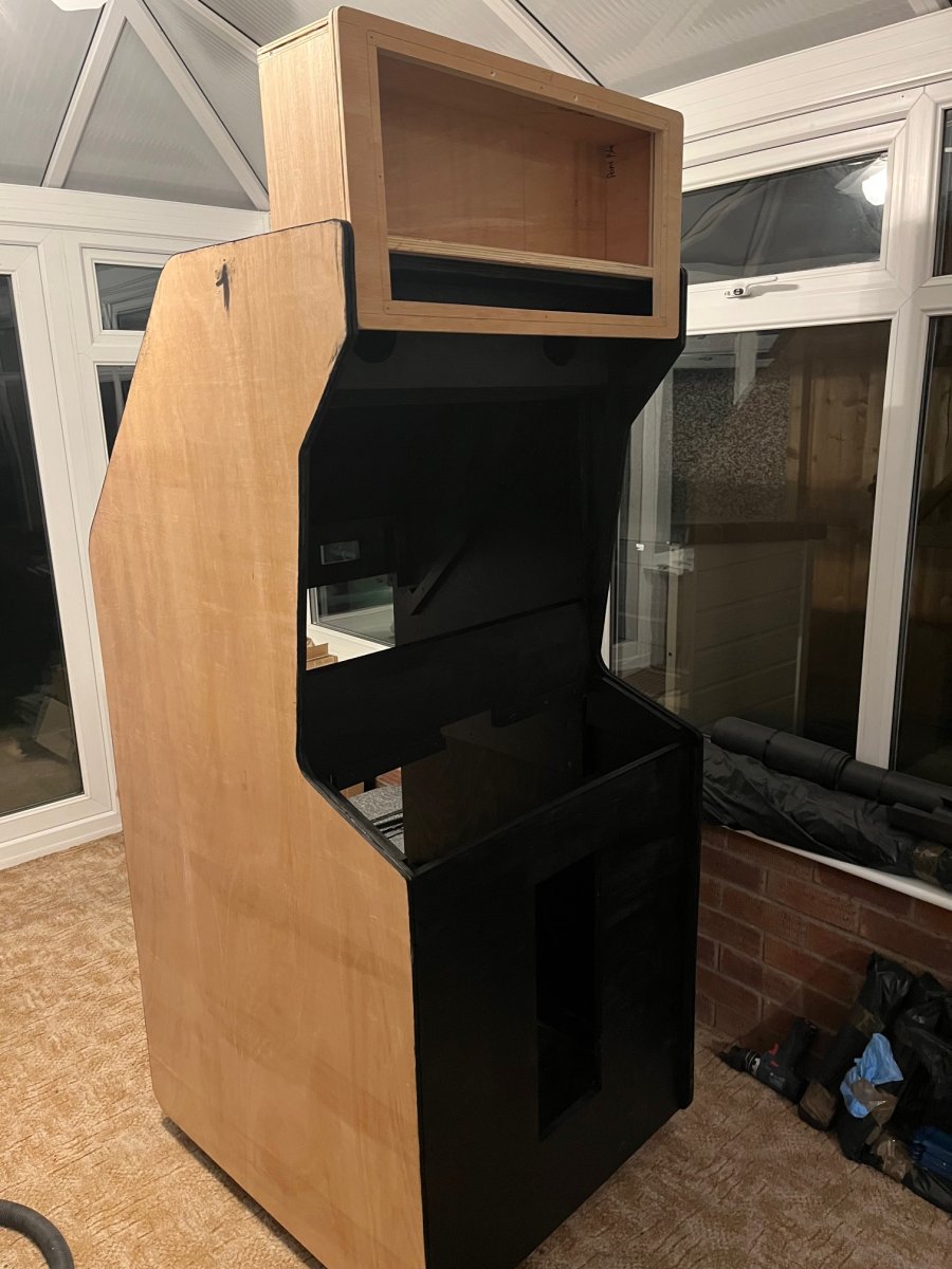
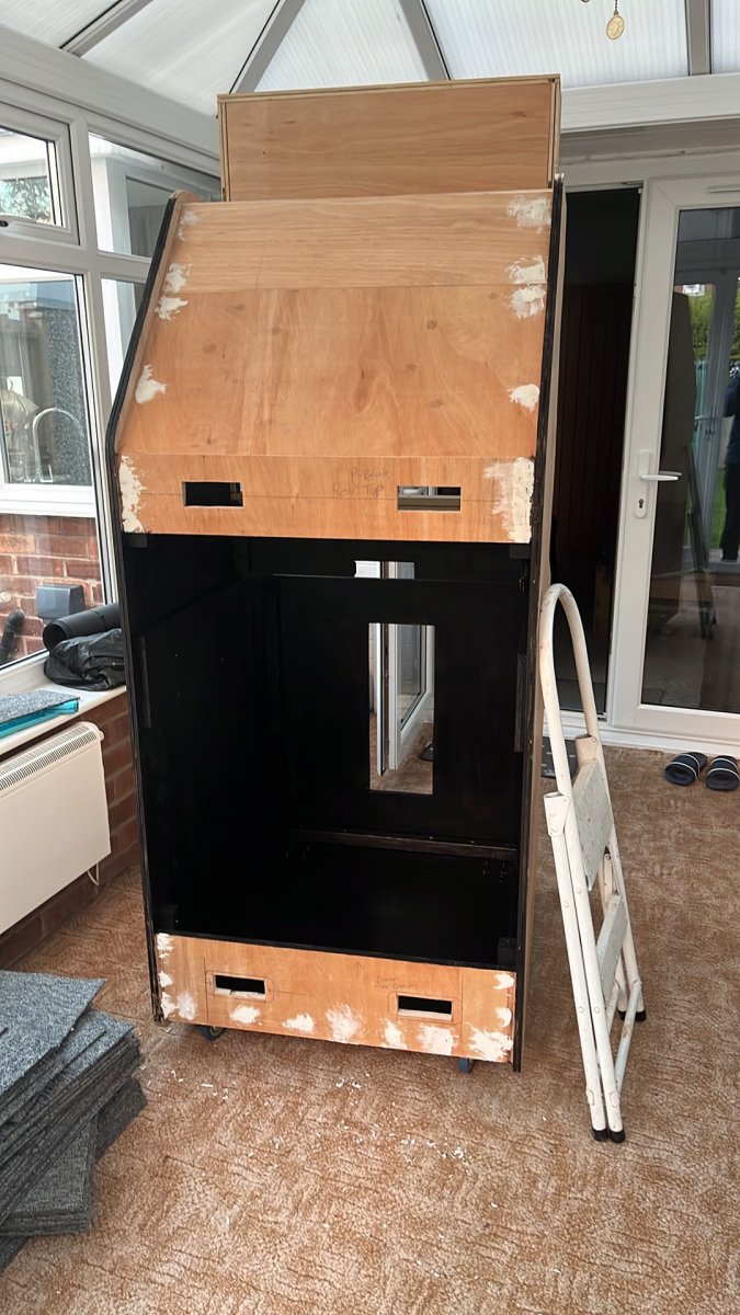
I have started on the Cabinet so If using a MiSTER wont work i'll just Save Up for a Point Blank 2 PCB
Here is a info dump of everything so far.
A Mister connects to an Arcade Monitor, an arduino is needed to fire the solenoids when trigger is pressed, a Playstation SNAC has to be used to connect the light guns to the mister, everything else is arcade hardware.
MiSTerFPGA Core: Namco System 12 Core beta 4 by XelaNotPu
https://www.patreon.com/XelaNotPu/posts/namco-system-12-172302772
The Namco arcade gun also features a thicker green cable that is used to earth the Solenoid.
Note: You must run a ground wire from the Arduino GND pin to the PSX SNAC ground (or the gun's black ground wire). This links the two systems together so the Arduino can see when the trigger line drops to 0V
Fit a 1N4007 diode with silver stripe facing OUT+ & Plain Side of the diode to OUT-
MiSTer Settings
The MiSTER needs to be told to output 15Khz for the Arcade monitor and to send the combined Sync and gun optical sensor.
You do not need to connect the monitor sync to the SNAC on the multisystem2
Ensure the mister.ini config is set to: composite_sync=1
When you connect the Arduino to the MiSTEr for the first time you need to connect a usb keyboard and press F12 then scroll down to Serial Mode / SNAC and change from None to Enabled. In the FPGA Core set the gun type mapping to GunCon.
Will this even work?
I welcome any advice
Any Questions just ask!
The Brief : Build an Arcade Cabinet that Plays Point Blank 1 , 2, 3 and Ghoul Panic using a CRT and Original Recoil Namco Guns
I have started on the Cabinet so If using a MiSTER wont work i'll just Save Up for a Point Blank 2 PCB
Here is a info dump of everything so far.
A Mister connects to an Arcade Monitor, an arduino is needed to fire the solenoids when trigger is pressed, a Playstation SNAC has to be used to connect the light guns to the mister, everything else is arcade hardware.
MiSTerFPGA Core: Namco System 12 Core beta 4 by XelaNotPu
https://www.patreon.com/XelaNotPu/posts/namco-system-12-172302772
Parts Needed | ||
Qty | Item Description | Notes |
2 | Namco Original Arcade Guns with 6 pin plugs | Player 1 and 2 |
1 | 24v Power Supply | Mean Well |
1 | Arcade Cabinet with Mirror, coin door, Bezel glass, control panel, 2x gun holsters, 2x 51mm Arcade Buttons 1x Blue and 1x Red with LEDS | |
1 | Jamma Cable | To spice cables into rather than soldering to the Jamma Port |
1 | 15khz Monitor 28” | Hantarax Polo |
1 | Heber Multisystem 2 arcade edition VGA out | £270 |
1 | Mean Well 5v 4A Power Supply | To power the Mister |
1 | Heber SNAC Classic Cartridge or compatible PSX SNAC adapter with 2 ports and RF | To connect the light guns |
2 | PlayStation extension cables to butcher | |
1 | Molex 2139 4 way | Pre Wired connector to connect to L & R Speakers |
1 | Arduino AtMega32u4 | Acts as a USB HID Device to the mister |
1 | Arduino Screw terminal expansion board | Makes connections easier |
1 | 64 to 512GB Fast SD Card | Formatted to correct file type |
2 | Dual MOSFET / XY-MOS 5-36V 15A 400W | The Arduino sends a low power voltage to trigger the Solenoid on the Arcade Gun when the trigger is pressed. Features Screw terminals and circuit protection. 1 for Each Gun. |
1 | VGA to screw terminal adapter | To allow the signal from the gen sensor to connect to the C-Sync of the Monitor |
2 | 1N4007 diodes | One across the output to protect circuit |
2 | Inline Fuse Holder | Protection |
2 | Fuse | Protection |
1 | Multisystem2.Ini file | To control the FPGA |
Namco Arcade Gun Wiring | |||
| Pin | Colour | Description | Connects to |
| 1 | White | Optical Sensor Signal | PlayStation Controller Pin 9 (Player 1 Gun to Port 1 & Player 2 Gun to Port 2) |
| 2 | Red | +5VDC to power the optical sensor | 5V Pin on Arduino |
| 3 | Yellow | 24v Recoil Constant +24VDC | MOSFET / Relay OUT + Pin |
| 4 | Black | Ground | GND Pin on Arduino (Shared with VGA Video GND PIN 10) |
| 5 | Blue | Trigger Switch | Digital Pin 2 on Arduino |
| 6 | Orange | Gun Solenoid Negative switched ground | MOSFET OUT - Pin |
The Namco arcade gun also features a thicker green cable that is used to earth the Solenoid.
Additional Wiring | |||
Original Namco Pin | Original Namco Wiring Colour | Function | Connects to |
1 | Red | Unused | |
2 | Red | Unused | |
3 | Orange | Player 1 Gun Solenoid | |
4 | Brown | Player 1 Start Lamp (Red Arcade Button) | Player 1 LED Lamp on Arcade Cabinet |
5 | White | Player 1 Gun Sensor | |
6 | Black | Ground (Shared) | |
7 | Pink | Player 2 Gun Solenoid | |
8 | Purple | Player 2 Start Lamp (Blue Arcade Button) | Player 2 Lamp on Arcade Cabinet |
9 | Grey | Gun 2 Sensor | |
10 | Blue | Unused | |
Arduino Wiring | |||
| Pin | Colour | Function | Connects to |
| D4 | Blue | Player 2 Gun Trigger Press | Player 2 Trigger Microswitch |
| D2 | Blue | Player 1 Gun Trigger Press | Player 1 Trigger Microswitch |
| D3 | White | Player 1 MOSFET PCB Output | Player 1 MOSFET TRIG |
| GND | Black | Arduino GND | Player 1 MOSFET GND |
| GND | Black | Arduino GND | Player 2 MOSFET GND |
| D5 | White | Player 2 MOSFET PCB Output | Player 2 MOSFET TRIG |
Note: You must run a ground wire from the Arduino GND pin to the PSX SNAC ground (or the gun's black ground wire). This links the two systems together so the Arduino can see when the trigger line drops to 0V
MOSFET Trigger Switch | |||
| Pin | Wire Colour | Function | Connects to |
| VIN + | Yellow | External +24v DC PSU | PSU +24v DC |
| VIN - | Black | External -24 DC PSU Negative GND | PSU GND |
| TRIG / PWM | White | Arduino Digital Pin 4 | Arduino Digital Pin D4 |
| GND | Black | Any Arduino GND Pin | Arduino Ground Pin |
| VCC | None | Leave Completely Disconnected | |
| OUT + | Yellow | Load positive wire + | Connect to the gun's solenoid positive lead (or bridge from VIN+) |
| OUT - | Orange | Load Negative - | Orange Wire on Arcade Gun |
Fit a 1N4007 diode with silver stripe facing OUT+ & Plain Side of the diode to OUT-
PlayStation Controller Port Player 1 & 2 | | |||
Pin | Sony Wire Colour | Function | Connects to | Arcade Gun Pin & Colour |
1 | Brown | Data | Not used | NA |
2 | Orange | Command | Transmits Trigger Press | |
3 | Grey or Violet/Purple | Vibration motor 7.6vdc | Not used | NA |
4 | Black | Common ground for optics and switch | | Pin 4 Black |
5 | Red | +5VDC | Red wire on Gun Sensor | Pin 2 Red |
6 | Yellow | Attention / Chip Select | Not used | NA |
7 | Blue | Clock | Not used | NA |
8 | Not used | Often omitted | Not used | NA |
9 | Green | | White wire on Gun Sensor (V-Sense Signal) | Pin 1 White |
MiSTer Settings
The MiSTER needs to be told to output 15Khz for the Arcade monitor and to send the combined Sync and gun optical sensor.
You do not need to connect the monitor sync to the SNAC on the multisystem2
Ensure the mister.ini config is set to: composite_sync=1
When you connect the Arduino to the MiSTEr for the first time you need to connect a usb keyboard and press F12 then scroll down to Serial Mode / SNAC and change from None to Enabled. In the FPGA Core set the gun type mapping to GunCon.
Will this even work?
I welcome any advice
Any Questions just ask!
Last edited:

 y != lastY) {