Sega Outrun 2 restoration.

Hello again.
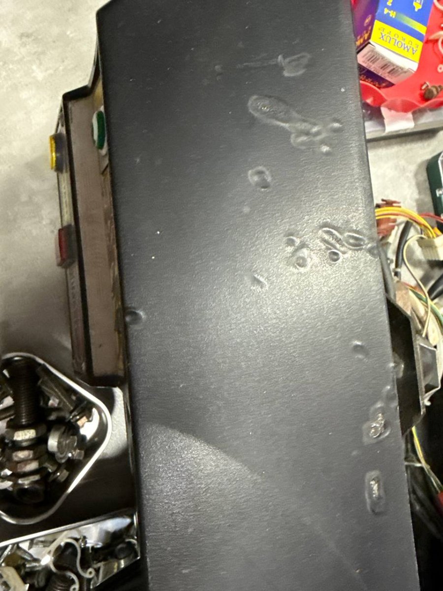
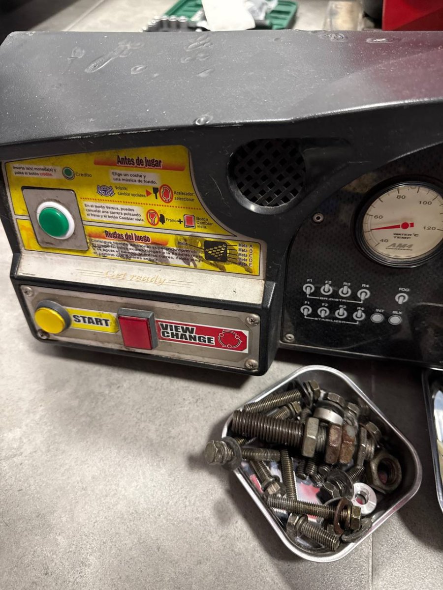
I have a new question to continue with the restoration. I have a dashboard burned by cigarettes. The condition is very bad. I have the possibility of getting a Daytona 2 dashboard without burns. Is it possible to swap the dashboard casing? Or is it totally impossible? I know I have to change both the gear lever and the button panel, but the question is if it is plug and play.

I leave photos of my burned dashboard and of a Daytona 2
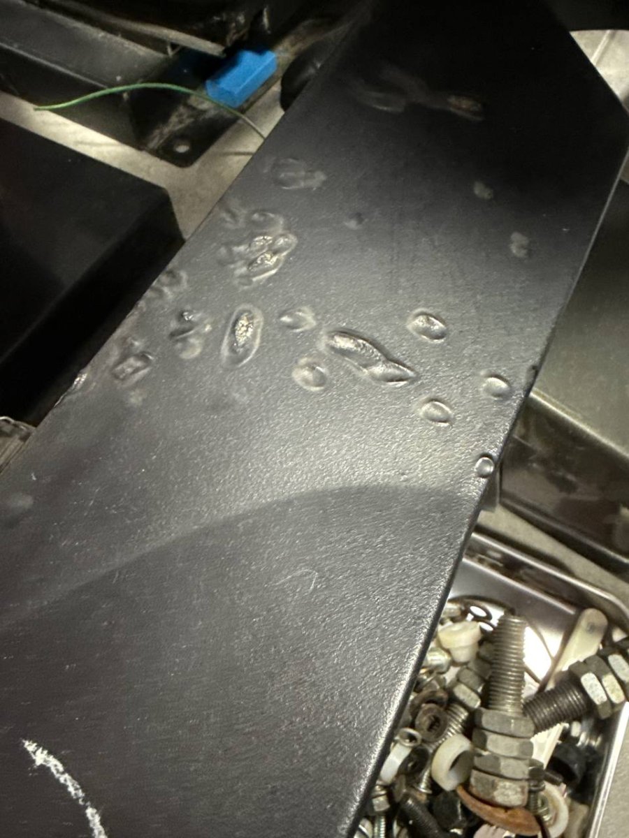
quemaduras1.jpg


quemaduras2.jpg


quemaduras3.jpg


Here I also leave a photo of a Daytona2 dashboard, and I am curious if the casing is the same for all and if I can use one without burns, putting all my parts in it.
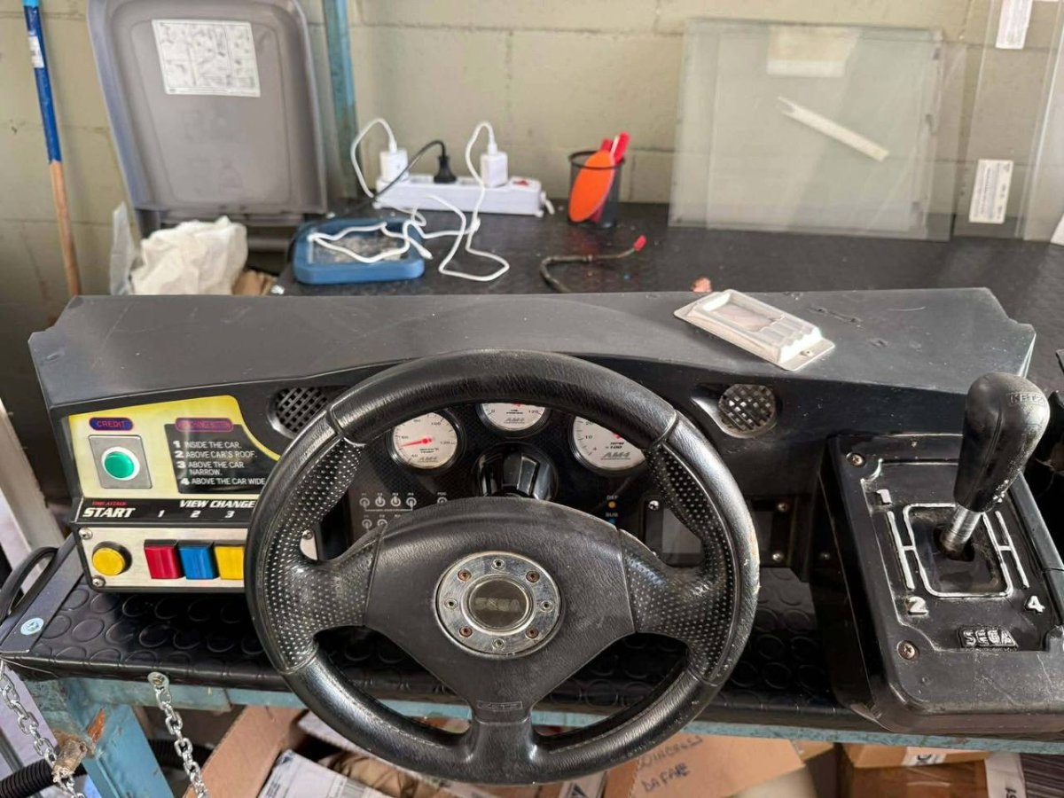

donante.jpg


Thank you for any help with this question. :thumbsup::thumbsup::thumbsup::thumbsup:
 
It's the same, yes.

However, there's burn marks on the Daytona dash as well, and what looks like an ash tray.

Considering the Daytona dash is hardly mint either, I would try sanding, filling and painting the OutRun 2 dash.
 
Hello everyone.

I have made quite a bit of progress in restoring the Master side. Today I wanted to do a first test power-on, using a computer monitor instead of a CRT, to facilitate trial and error. At first, I connected the machine and the monitor to the power and got absolute silence. Neither the fans turned on, nor did it do a flywheel test, nor did the Chihiro turn on, nor absolutely anything. The test lasted 4 seconds.
He's not in the photo, but before the test I connected the Chihiro's VGA cable to the computer monitor


photo_8_2026-05-24_20-30-08.jpg


photo_6_2026-05-24_20-30-08.jpg


After checking grounds, checking the fuse that goes along with the power outlet at the back of the furniture, checking absolutely everything I could think of, I asked Google AI. After sharing the electrical diagram with it and asking it to do a thorough investigation of said diagram, the AI tells me that if I don't connect the coin mechanism, it won't start because the electrical circuit is open.

Since it seems that the electrical diagram has been studied thoroughly, I went to the warehouse to get the coin tower/service and brought its wiring.
I connected the wiring to the coin box and to the arcade machine. I turned on the power and absolute silence.
After reviewing the coin box wiring again, I began to wonder if I had connected the part that goes to slave to the master and that is why it does not start, since I reversed the connectors and turned on the power. Absolute silence.

I am leaving photos for better understanding, but I find myself again in a dead end. I don't know which cables are Slave or Master, I don't know why it won't turn on. If anyone can shed some light, don't hesitate to post it.


COIN/SERVICE WIRING:

photo_5_2026-05-24_20-30-08.jpg


COIN BOX REAR CONNECTIONS:


photo_2_2026-05-24_20-30-08.jpg


MASTER AND SLAVE CONNECTIONS:


photo_4_2026-05-24_20-30-08.jpg


REAR PART OF THE MASTER CABIN:


photo_7_2026-05-24_20-30-08.jpg


photo_3_2026-05-24_20-30-08.jpg


I have doubts about which side of the wiring goes to master, the one with the red connector that goes to the red on the arcade? Or the one that is white and goes to the red on the arcade? Which is the input in the coin box, the white cables or the black ones? When I press the black power button on the arcade, which is located right below the power cable, you hear the typical electric crackle, but nothing at all works.
Thanks to all.
 
From my wiring experience with my naomi/chihiro cab, sky blue wires/pink wires are run power and go hand in hand with black/white wires (green/yellow wires are ground). Blue is the same as black, and White goes with pink (at least thats how I have mine when I rewired my entire slave cab)

Maybe check the Naomi Fuse/power connector that I have in mine (see picture below, I think yours is above the transformer). The back of the cab where the electrical plug goes is wired directly to this connector and from there everything in the cab is powered (JVS board, transformer, Sun PSU etc)

I think I read somewhere that Slave cabs actually draw a good majority of their power from the Master.

Also I'm in the US not in Europe so I'm not sure how that would differ.
 

Attachments

  • 838-11856-01-UL.jpg
    838-11856-01-UL.jpg
    152.7 KB · Views: 31
Hello everyone.
I have made a little progress.
To begin with, I found that the transformer fuse was dead. Since it is soldered, I put the Slave's circuit on it. I will go buy fuses of this type later. It was the only fuse I didn't check, and it just happened to be the one that was preventing the power supply from having current. Thanks to the colleague from the previous message @bgwelistyl , I went to check it.

This gave me a small advance but I still have electrical problems.
After checking all the wiring with the multimeter, reviewing every connection again, and even trying a different power supply and a different Chihiro.... I didn’t know what else to do. The problem was basically that the power supply was giving me all the correct voltages, but they were lost in the current filter. Something was drawing the current, even to the point of killing the power supply.

Since the problem started from the power supply, I decided to disconnect everything and start connecting one by one. When I connected the filter with nothing attached to it, the green lights on the filter turned on. Big progress, since until now I had never had green lights. Then I connected the Chihiro and again, total blackout. So I disconnected everything from the Chihiro. No gdroom, no cables of any kind. Then the Chihiro turned on!!! Great, finally some progress. Now I connect the video cable and an image appears on the monitor....


photo_5_2026-05-26_23-12-23.jpg


Great, we have video. Now an error comes up about no connection with the Gdrom. So I connect the power cable from the Gdrom to the Chihiro and... goodbye power, darkness again. Well, it occurs to me that maybe the cable is bad and is causing a short. I go to my cable box and find another one that looks new. I plug it in and goodbye power. So who is the culprit? If it’s not the cable, who is the culprit? The Gdrom?

After these small progresses, I must say that I did not get power on the dashboard, nor on the steering wheel, nor in the coin/service box, nor on the steering wheel fan. The force feedback blinks red, the I/O blinks red, and the audio amp is green.


photo_7_2026-05-26_23-12-23.jpg


photo_4_2026-05-26_23-12-23.jpg


My next step will be to try another GD-ROM to figure out that my drive is shorted. On the other hand, why don't I have power in the dashboard. coin box, or steering motor? Why do the FFB boards blink red along with the I/O?
I never thought that getting this project up and running would be so problematic.
Greetings, and comments and any ideas to test are appreciated.
 
Last edited:
Keep in mind this is on a naomi cab but FFB, JVS come from that Naomi pink/sky blue wires. The yellow/white/red wires power the GD Rom (and card reader)

Do you have the part 400-5421-07512 (i dont see it thats why im asking) ? I have that part in both machines and thats used to run the card reader/ GD Rom etc(i think it comes from the sun power supply)

I'm not sure how different the power supplies are between a US and EU cab but thats what I have in mine

What I ended up doing with my machine is just making an exact replica of the Master Cab and then just linking it up like that. I bought a used OR2 wiring harness set from Yaton and then a couple of missing parts and copied it.

Im not sure about the wiring diagram for chihiro but maybe look at an Outrun 2 wiring cab that fits a naomi, maybe that'll give you what you need
 
1779836562235.gif


Reminder: Sega often used Yellow for 5v and Red for 12v in their cabinet wiring. Are your 5v and 12v swapped going into the GDROM drive? If so then you almost certainly blew up the GDROM drive controller. This is usually fixable with a new controller chip (I've done it a few times), but unless you can do SMD rework then it's easier to find a new one, or go with a CF card solution.
 
also, the Naomi Sun Power supply have an additional 3rd connector/harness as well for the racing cabs
 
Keep in mind this is on a naomi cab but FFB, JVS come from that Naomi pink/sky blue wires. The yellow/white/red wires power the GD Rom (and card reader)

Do you have the part 400-5421-07512 (i dont see it thats why im asking) ? I have that part in both machines and thats used to run the card reader/ GD Rom etc(i think it comes from the sun power supply)

I'm not sure how different the power supplies are between a US and EU cab but thats what I have in mine

What I ended up doing with my machine is just making an exact replica of the Master Cab and then just linking it up like that. I bought a used OR2 wiring harness set from Yaton and then a couple of missing parts and copied it.

Im not sure about the wiring diagram for chihiro but maybe look at an Outrun 2 wiring cab that fits a naomi, maybe that'll give you what you need


Hello.

Basically, I think that the difference between an American arcade and one in the EU is the transformer that converts the current from 220 to 110. Apart from that, I think they are exactly the same.

As for Slave, yes, that is exactly what I plan to do, when I get the Master to work one hundred percent, I will replicate everything in the Slave.

:D


1779836562235.gif


Reminder: Sega often used Yellow for 5v and Red for 12v in their cabinet wiring. Are your 5v and 12v swapped going into the GDROM drive? If so then you almost certainly blew up the GDROM drive controller. This is usually fixable with a new controller chip (I've done it a few times), but unless you can do SMD rework then it's easier to find a new one, or go with a CF card solution.


Hello.

I really liked your drawing and it cleared up a doubt I had. I have cables that come with six wires and others that only have four. When I bought them, supposedly all are GDROM, but I was very surprised by the difference between them.

Regarding the power supply, I am using a Sega 400-5397-01 power supply, which if I remember correctly are the ones that came in the Sega Naomi universal cabinet. According to what I have found on the internet, these power supplies are compatible with my current setup in Chihiro. If not, I will try to find another power supply, which I might have from a Sega Kart Club.

The last point you mentioned about reversing the power cable, I tried it with the arcade completely without electricity, connecting the connector incorrectly, and it was not possible. I am sending you a photo of how I have it, with the red cable on the right. I am sending photos of the power supply and the cable. Thank you very much for your drawing and your message.
:):)


photo_3_2026-05-27_20-28-05.jpg


photo_2_2026-05-27_20-28-05.jpg


photo_1_2026-05-27_20-28-05.jpg


also, the Naomi Sun Power supply have an additional 3rd connector/harness as well for the racing cabs

I have the three connectors hooked up, it's correct. As I said before, my power supply is from a universal Sega Naomi cabinet, but I understand that it is completely compatible with the Chihiro system. :)


you could also try a cf card and get rid of the GDrom

Notice that I had that idea discarded, precisely because I have the GD-ROMs with the original game and its original key. But if this is going to be giving failures or problems, the safest thing is probably to implement the system you recommend. Thank you very much for the suggestion..:)
 
Last edited:
Hello.

I really liked your drawing and it cleared up a doubt I had. I have cables that come with six wires and others that only have four. When I bought them, supposedly all are GDROM, but I was very surprised by the difference between them.

Regarding the power supply, I am using a Sega 400-5397-01 power supply, which if I remember correctly are the ones that came in the Sega Naomi universal cabinet. According to what I have found on the internet, these power supplies are compatible with my current setup in Chihiro. If not, I will try to find another power supply, which I might have from a Sega Kart Club.

The last point you mentioned about reversing the power cable, I tried it with the arcade completely without electricity, connecting the connector incorrectly, and it was not possible. I am sending you a photo of how I have it, with the red cable on the right. I am sending photos of the power supply and the cable. Thank you very much for your drawing and your message.
:):)
Not my drawing but glad it was helpful. Yes, some cables have 6 and some only have 4. The GDROM drive does not pull a ton of power so it is OK to use 4.

You can't trust that wire color means any voltage in particular. Unplug the connector from the GDROM drive and measure the power with a multimeter between the white and the yellow, and the white and the red. What voltage are you getting for each?
 
Not my drawing but glad it was helpful. Yes, some cables have 6 and some only have 4. The GDROM drive does not pull a ton of power so it is OK to use 4.

You can't trust that wire color means any voltage in particular. Unplug the connector from the GDROM drive and measure the power with a multimeter between the white and the yellow, and the white and the red. What voltage are you getting for each?
Hello.
I've discovered something strange. On the Chihiro I was using, when I put the multimeter between the 5V line and neutral, it beeps. On the other Chihiro, it doesn't. This means that the Master Chihiro has, for some reason, the 5V line that powers the GD-ROM switched. The readings I got on the other Chihiro were 11.9V and 5.1V.
 
Another thing I have been testing is 3 gdrom units. I managed to get one to work and it gave me the error of "This game is not aceptable by main board" I have performed a test on Chihiro and have obtained the following:

photo_1_2026-05-28_16-51-32.jpg


photo_4_2026-05-28_16-51-32.jpg


photo_2_2026-05-28_16-51-32.jpg


photo_3_2026-05-28_16-51-32.jpg


photo_6_2026-05-28_16-51-32.jpg
 
Hello.
The RAM problem was solved simply by removing the module and putting it back in its place again. I suppose it was just some stubborn connection.
While I solve other electrical problems in the coin box, I have started to run some tests on the Chihiro to see how the steering wheel, motor, etc. are working.

Should the center of the steering wheel change the parameter? And engine power? Both can be modified.


photo_1_2026-06-08_16-23-16.jpg


photo_2_2026-06-08_16-23-16.jpg


I will update with the following progress on the electrical topic. I am going to put the CRT in its place now and I am going to start assembling all the panels and plastics to get closer to finishing the Master cabinet.

All comments are welcome.
:) :):):)
 
Last edited:
Back
Top